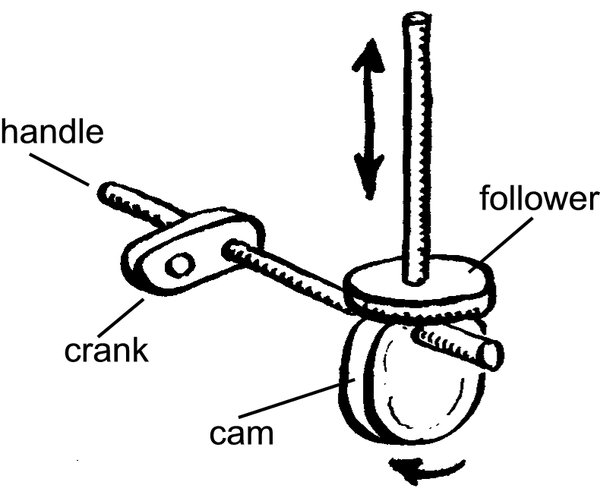
Cams, change one type of motion into another. There are two types, linear and rotary. Rotary cams are very common in machines and are used to change rotary motion into reciprocating motion. Cams are asymmetrical forms that are fixed on a rotating shaft. The form, size and position of the shaft in the cam will determine the distance and movement of the output shaft attached to the follower. A follower follows the cam that gives the desired output.
Rotary or circular cams
These cams change rotary motion into reciprocating (backwards and forwards) motion. They are usually made from metal or plastic and are fitted on a shaft. A spring or the weight on the follower keeps it on the cam. Rotary cams can vary in shape from circular to heart and pear shapes.
Linear Cams
These cams change the direction of reciprocating motion. The cam can have any profile and moves backwards and forwards while the follower follows the profile. With these cams the follower normally has a small wheel to allow the movement to be smooth.
Input rotary motion can be obtained by fitting a crank to the handle. The output movement depends on various factors. The sketches below illustrate three different ways of getting output movement.
1. Cam operated – up and down movement
2. Friction wheel - shaft pins
3. Wheel and connecting rod
By applying the basic principles you can easily construct a hand operated mechanism without becoming too technical.
The Crank
The steam engine is a good example of the crank mechanism (crank/slider). The crank uses the wheel and axle principle. Can you all remember pedalling on your first tricycle? The wheel and pedal shaft is a good example of a crank.
Several crank handles can be put together to form a crankshaft. The crankshaft forms a very important function in basically every machine with moving parts. The pistons in a car are pushed up and down by the crankshaft.
Activity1
Make a simple sketch of a crank handle that you can use in a hand operated mechanical toy.
Draw three different shapes of cams. Also illustrate the difference each will have in the output movement.
Give two examples where cams and cranks are used in machines.
LO 2.3
Assessment
LO 2
TECHNOLOGICAL KNOWLEDGE AND UNDERSTANDING The learner will be able to understand and apply relevant technological knowledge ethically and responsibly.
We know this when the learner:
systems and control:2.3 demonstrates knowledge and understanding of interacting mechanical systems and sub-systems by practical analysis and represents them using system diagrams:
gear systems;
belt drive pulley systems with more than one stage;
mechanical control mechanism (e.g. ratchet and pawl, cleats);
pneumatic or hydraulic systems that use restrictors;
one-way valves;
systems where mechanical, electrical or pneumatic or hydraulic systems are combined;