

| << Chapter < Page | Chapter >> Page > |
PROBLEMS
This lecture note is based on the textbook # 1. Electric Machinery - A.E. Fitzgerald, Charles Kingsley, Jr., Stephen D. Umans- 6th edition- Mc Graw Hill series in Electrical Engineering. Power and Energy
1.1 A magnetic circuit with a single air gap is shown in Fig.1.1. The core dimensions are:
Cross-sectional area Ac =
Mean core length lc = 0.6 m
Gap length g = 2.3 x m
N = 83 turns

Figure 1.1 Magnetic circuit.
Assume that the core is of infinite permeability ( ) and neglect the effects of fringing fields at the air gap and leakage flux. (a) Calculate the reluctance of the core and that of the gap . For a current of i = 1.5 A, calculate (b) the total flux , (c) the flux linkages ) of the coil, and (d) the coil inductance L.
1.2 Repeat Problem 1.1 for a finite core permeability of .
1.3 Consider the magnetic circuit of Fig.1.1 with the dimensions of Problem1.1. Assuming infinite core permeability, calculate (a) the number of turns required to achieve an inductance of 12 mH and (b) the inductor current which will result in a core flux density of 1.0 T.
1.4 Repeat Problem 1.3 for a core permeability of .
1.5 The magnetic circuit of Problem 1.1 has a nonlinear core material whose permeability as a function of is given by
where is the material flux density.
a. Using MATLAB, plot a dc magnetization curve for this material ( vs. ) over the range 0 2.2 T.
b. Find the current required to achieve a flux density of 2.2 T in the core.
c. Again, using MATLAB, plot the coil flux linkages as a function of coil current as the current is varied from 0 to the value found in part (b).
1.6 The magnetic circuit of Fig.1.2 consists of a core and a moveable plunger of width , each of permeability . The core has cross-sectional area Ac and mean length . The overlap area of the two air gaps Ag is a function of the plunger position x and can be assumed to vary as
You may neglect any fringing fields at the air gap and use approximations consistent with magnetic-circuit analysis.
a. Assuming that , derive an expression for the magnetic flux density in the air gap as a function of the winding current I and as the
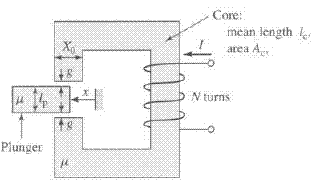
Figure 1.2 Magnetic circuit for Problem 1.6.
plunger position is varied ( ). What is the corresponding flux density in the core?
b. Repeat part (a) for a finite permeability .
1.7 The magnetic circuit of Fig.1.2 and Problem 1.6 has the following dimensions"
g = 0.8 mm
= 2.5 cm N = 430 turns
a. Assuming a constant permeability of , calculate the current required to achieve a flux density of 1.3T in the air gap when the plunger is fully retracted (x =0).
b. Repeat the calculation of part (a) for the case in which the core and plunger are composed of a nonlinear material whose permeability is given by
where is the magnetic flux density in the material.
c. For the nonlinear material of part (b), use MATLAB to plot the air-gap flux density as a function of winding current for x = 0 and x = 0.5 .
Notification Switch
Would you like to follow the 'Electrical machines' conversation and receive update notifications?

|
|

|
|

|
|

|
|

|
|

|
|

|
|
|
|
|

|
|

|