This module demonstrates the use of the c28x peripherals and DMC library blocks to control the speed of a DC motor in a closed-loop fashion. This example is based on the "DC Motor Speed Control via RTDX" SIMULINK demo.
Introduction
This chapter demonstrates the use of the c28x peripherals and DMC library blocks to control the speed of a DC motor in a closed-loop fashion. This example is based on the "DC Motor Speed Control via RTDX" SIMULINK demo.
The target speed of the motor is set by the user in the MATLAB GUI. This value is fed to the Controller (based on the eZDSP-F2812) to change the motor speed. The loop is closed by a tachometer. The controller constantly adjusts the value of the DC voltage applied to the motor to maintain the desired speed. The control loop is shown in the following figure:
DC Motor Control Loop
The Speed controller comprises two blocks (please refer to Figure 2):
This block compares the desired speed with the measured speed and generates a digital value proportional to the DC value to be applied to the motor.
The Speed Controller
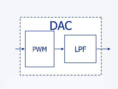
This block is implemented using a PWM signal generator and a Low Pass Filter as shown in Figure 3. This method is described in .The output voltage, generated at the LPF output will be:
Where:
- Generated Voltage
- PWM Duty Cycle
- Supply Voltage (3.3 V)
Digital to Analog Converter Implementation
Figure 4 shows the loop control implementation, based on three components:
eZDSP-F2812 (Please refer to )
Interface circuit (Please refer to Section )
DC Motor Kit (Please refer to Section )
DC Motor Control Loop Implementation
Setup
This demo is based on the Spectrum Digital eZdsp-F2812 that is connected to a DC Motor Kit through a dedicated interface circuit. The setup is shown in Figure 5.
Setup
The dc motor kit
Servo amplifier [sa150d]:
This unit operates the motor from signals applied to the input sockets 1 or 2, enabling control of the motor speed and reversing its rotation. This example shows speed control only, and will make use input socket 1 only. The servo amplifier is connected to the servo motor by an 8-pin plug and able. Terminals for ± 15 volts and ground (common) are available on this unit.
Servo motor with tachometer [mt150f]:
This unit is a DC motor that produces a torque of the order of 8 oz-in (600 gm-cm) at 2A input current. The inertia is about 3x10⁻⁵ Kg −m2. The output shaft may be fitted with a brake disc and/or an inertia disc to load the motor. A second shaft on the side of the motor is coupled to the main shaft by 30:1 gears (the smaller shaft rotates slower than the main shaft). The tachometer with terminals +, - and common (ground) is attached to the motor.
Power supply [ps150e]:
This unit provides the various voltages supplies required for the servo components. There are terminals for ±15 volts, and common (ground). An ammeter is also included. The maximum current is 2 A. An 8-pin socket and cable connects this unit to the servo amplifier.
Receive real-time job alerts and never miss the right job again
Source:
OpenStax, From matlab and simulink to real-time with ti dsp's. OpenStax CNX. Jun 08, 2009 Download for free at http://cnx.org/content/col10713/1.1
Google Play and the Google Play logo are trademarks of Google Inc.
Notification Switch
Would you like to follow the 'From matlab and simulink to real-time with ti dsp's' conversation and receive update notifications?