This module contains the Elec 220 lab 4, which covers basic interrupt usage on the TI MSP430 microcontroller at the assembly language level.
Msp430 interrupts and subroutines: your tasks
This week you will learn more about the philosophy of interrupt driven programming and specifically how interrupts work on the MSP430. To test out your knowledge, you'll write another simple I/O echo program that builds off the code from the last lab.
Coding in MSP430 Assembly,
create an interrupt driven I/O echo program . The program should read the values of the input DIP Switches(P9.4-P9.7) when one of the pushbuttons (P3.6 or P3.7) triggers an interrupt, and then output the read value to the 7 segment display (P4.0-P4.3).
Details
Background information
A few more instructions
Like you saw in the
GPIO Lab , the MSP430 (even though it's a RISC
R educed
I nstruction
S et
C omputing processor) has a fair number of instructions in addition to those you learned for the LC-3. The extra instructions help programmers simplify code readability and streamline program execution.
You've already seen how the MSP430 uses memory access modifiers and the general purpose
mov instruction to implement all the functionality of the LC-3's plethora of load and store instructions. Two other very useful MSP430 instructions are
bis (
Bi t
S et) and
bic (
Bi t
C lear). These instructions take an operand with "1"s in the bits you wish to set or clear, and then a destination upon which to do the operation. This comes in handy when you need to modify a few specific configuration bits out of a whole register (like the GIE bit in the SR for interrupts... see below!). The header file has pre-defined masks you can use with
bic and
bis to make bit operations much more readable.
The
bis and
bic instructions actually emulate functionality you already had with
and ,
inv , and
or .
Assembler and Compiler Directives sound intimidating, but they are nothing more than bits of code intended for the assembler/compiler itself. Directives allow you to specify how the assembler/compiler handles your code and how it all finally comes together into the executable binary file.
The skeleton file has included several directives all along--
.cdecls C,LIST, "msp430f5637.h" tells your .asm file to include the c code header aliases from the generic MSP430G2231 configuration file.
.text tells the assembler to place your program in the main flash memory section, and
.sect "reset" defines where to start the program after a processor restart.
Continuously polling a pin for input wastes useful CPU cycles and consequently uses more power
The CPU must check the pin often enough to detect a change-- when trying to catch a rapidly changing digital signal (a small pulse or transient, etc.), polling may not be sufficient.
In conclusion, polling is easy to understand and implement, but is generally inefficient.
The solution... interrupts
Interrupts use dedicated hardware to detect input changes or hardware events (button pushes, timer intervals, etc...)
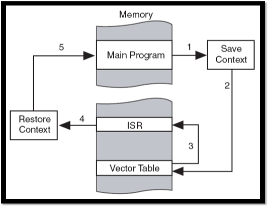
When a change is detected, the interrupt logic interrupts the CPU execution.
The CPU stops what it is doing and calls a special section of code determined beforehand in the interrupt vector table. This section of code is known as the
I nterrupt
S ervice
R outine, or ISR for short.
Once the interrupt has been serviced and the ISR is complete, the CPU returns to what it was doing before.
The way the main program pauses execution and then branches to a new section of code works in a similar way to the LC3's Traps.
Advantages to interrupts
Interrupts will catch quickly changing inputs (within reason) that polling might have missed.
The CPU is allowed a level of freedom to multitask without needing to "worry" about explicitly catching input changes. The CPU can do other tasks safely while waiting for an interrupt to fire.
Programs can be "interrupt driven," meaning that the program is just a collection of different interrupt service routines for different tasks.
The CPU is only active while servicing an ISR, allowing it to go into low power mode between interrupts. Programs that spend a large percentage of their run time waiting on outside events can be made
much more power efficient .
Basic interrupt implementation
Discrete hardware detects interrupt conditions and then triggers the appropriate interrupt in the CPU if it is high enough priority.
The interrupt vector table maps each interrupt to the memory address of its interrupt service routine. Like with traps, the CPU first goes to this table to find the address of the ISR and then jumps to the actual ISR code.
CPUs contain several different interrupts to handle different external events uniquely.
Msp430 interrupt call procedure
Interrupts on the msp430
On the MSP430, there are two types of interrupts: maskable and non-maskable.
Maskable Interrupt
Most interrupts are maskable. Maskable interrupts can be enabled or disabled as a group by setting the GIE (
G eneral
I neterrupt
E nable) bit in the status register. The interrupts must also be enabled individually, but masking allows delicate code (For example, if you are running a precisely timed output routine that must execute all at once) to run in a near interrupt free state by disabling only one bit.
Enabling all maskable interrupts
bis.w #GIE, SR
Non-Maskable Interrupt
Non-Maskable interrupts will trigger an interrupt at any point in code execution-- they cannot be enabled or disabled on a line by line basis, and they will execute even if the processor is "stuck". Non-maskable interrupts mainly deal with recovering from errors and resets (illegal memory accesses, memory faults, watchdog expiration, or a hardware reset will trigger non-maskable interrupts).
In the MSP430, GPIO interrupt capability must be enabled at the masking level as well as the individual pin enable level.
Interrupts should be enabled during the program initialization (before the main code loop or entering low power mode), but after any initialization steps vital to the ISR
There are four main steps to enabling interrupts on the msp430's gpio pins.
Enable interrupts on the individual input pin (in this example pin P1.4) using the port's interrupt enable register.
bis.b #010h,&P1IE P1IE=
P ort
OneI nterrupt
E nable
Select whether the interrupt triggers on a transition from low->high ("0") or high->low ("1") using the port's edge select register
bis.b #010h,&P1IES P1IES=
P ort
OneI nterrupt
E dge
S elect
Clear the interrupt flag on the pin in the port's interrupt flag register.
bic.b #010h,&P1IFG P1IFG=
P ort
OneI nterrupt
F la
G
Flags are important. For one, if you forget to clear the flag at the end of your ISR, you will just trigger another interrupt as soon as you return. Also, all of the GPIO pins trigger the same port one ISR. If you have multiple interrupt triggering pins, flags can allow you to determine which pins triggered the interrupt.
And lastly, only after all of your other important setup, enable all the maskable interrupts in the overall CPU status register.
bis.w #GIE, SR
Writing an msp430 interrupt service routine
The ISR needs to be a section of code outside of the normal main loop.
Your ISR must begin with a label and end with a
reti instruction.
Pin1_ISR<YOUR ISR CODE>bic.b #001h,&P1IFG
          reti
At the end of your .asm program, you need to tell the assembler to write the starting address of your ISR to the correct section of the interrupt vector table. The label at the beginning of your ISR allows you to find this address.
CCS5 uses a separate file to define different sections of your controller's memory. This extra layer of abstraction makes it easier to port code between different microcontrollers, but means that you the programmer can't write directly to a specific memory address in your program. To fill your vector table, you'll need to use the following syntax:
.sect MEMORYSECTION
.word DATATOPLACE/LABEL
The port one interrupt vector for the MSP430 G2231 is defined as 0xFFDE. If you look in the file "Lnk_msp430f5637.cmd" (in the file browser for your lab 4 project), you will see that address 0xFFDE has been assigned to int47. In the second half of the linker file, the section PORT1 has been assigned to memory addresses>int47.
When you want to write to the GPIO entry of the interrupt vector table, you need write to code section "PORT1" in your assembly file. You can do the same for different ports as well- in the escape platform you will likely use the push buttons on "PORT3"
Setting the gpio vector in the interrupt vector table for port3  .sect "PORT3"
.word Pin1_ISR
The
.sect instruction directs the linker to put the code that follows into a specific code section. (You have been using this all along, just putting your code into the main program ".text" section.)
The
.word instruction directs the linker to write a word length data value into memory.
Subroutines have a lot in common with interrupt service routines (in fact, many programmers use ISR interchangably between
I nterrupt
S ub
R outine and interrupt service routine).
Subroutines are sections of code you use repeatedly during a program-- they allow you to keep repetitive program sizes smaller by re-using the same code section instead of repeating it everywhere you need it.
To go to a subroutine, use the
call #SubroutineLabel instruction.
call is analogous to triggering an interrupt. Call works in practice a lot like just jumping to the label, but it also pushes the PC onto the stack (like an ISR) so you can return to wherever you may have left off (since multiple places in code can call the same subroutine).
At the end of your subroutine, use a
ret (
ret urn) instruction to pop the PC off the stack and go back to the original execution point of the main program. This is analogous to the
reti instruction at the end of an ISR.
Calling a subroutine on the MSP430
ONLY saves the PC, not the status register like an ISR. You can use subroutines to encapsulate complicated logic, and then examine the conditions afterwords in your main program.
There is a
slight performance trade off when using subroutines from the overhead involved with storing the PC and moving to a new section in memory, so use them intelligently.
A simple subroutine to demonstrate call and return:
<Your Other Code...>call #Sub220<Your Other Other Code...>Sub220  add R4, R5
        inv R5ret
Interrupt assignment detail
Your task is to create a simple MSP430 assembly program using CCS4 and the MSP430 LaunchPad to output a stored value to the 7-segment display. Your program should be
interrupt driven , and triggering an interrupt from one of the pushbuttons (Pin 3.6 or 3.7) should store and output a new output value corresponding to the state of the DIP Switches on Port9.4-9.7. Changing the switches should
not effect the output until pushing the button . Your program should consist of:
A setup section that configures the GPIO pins and enables interrupts.
An infinite main loop that does nothing (the
N o
Op eration instruction
nop could come in handy).
An ISR that takes the new inputs and writes them to the output before returning to the main loop.
Interrupt Diagrams Courtesy of TI document slau144e, "MSP430 User's Guide."