<< Chapter < Page Chapter >> Page >

There is a very large number of considerations that affect the selection of the best method of frequency-division demultiplexing signals in a particular application. As a result, it is virtually impossible to provide a simple cookbook methodology that always produces the best design. Even so, it is useful to systematically describe the design issues and choices evaluated so far in this technical note. Such a description, condensed into a design flowchart, is discussed in this section. Comparison of it with the design examples provided in the section "Example: Using an FDM-TDM Transmux to Demodulate R.35 Telegraphy Signals" and the section "The Impact of Digital Tuning on the Overall design of an FDM-TDM Transmux" shows excellent agreement. But while it is intended to be helpful, it must be used with care since relatively small differences in the application-dependent assumptions can influence the resulting choices quite considerably.

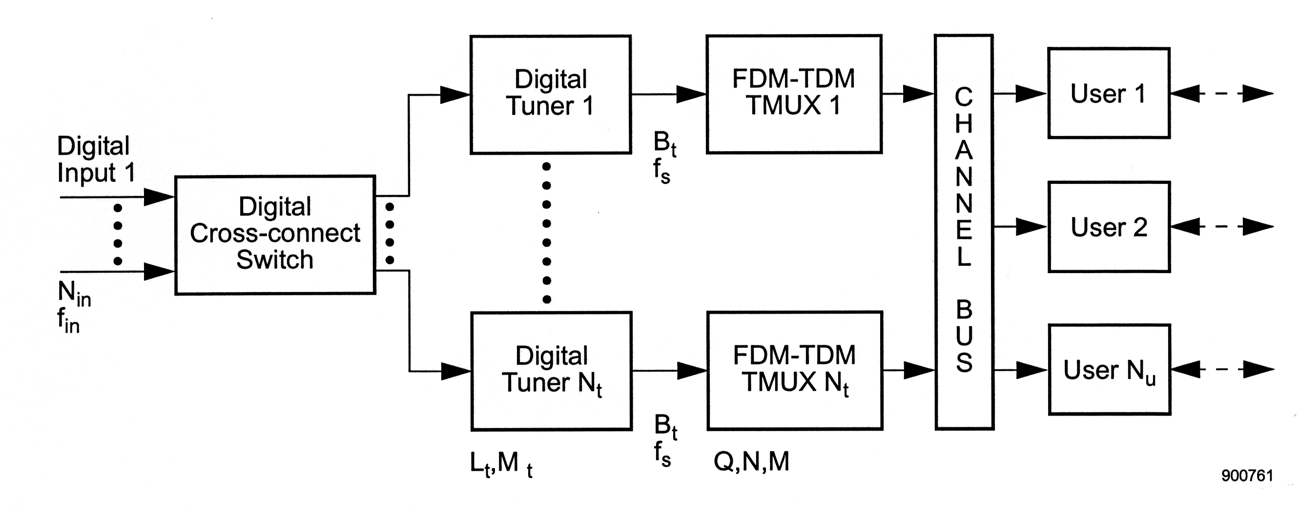
The decision flowchart presented in [link] assumes that the generalized demultiplexer has the block diagram shown in [link] . The system accepts N i n digitized FDM signals, all sampled at f i n Hz. These are made available to N t digital tuners. All of these tuners are of the same design, employ the same decimation factor M p and produce output samples at the same rate of f s Hz. The tuner outputs are transmultiplexed, sending their output channel samples to a bus, which up to N u user processes have access to. Since each transmux is fed by a tuner, there are N t transmuxes, each parameterized by Q , N , and M .

On the one hand, this architecture is not perfectly general, since parameters such as filter bandwidths are assumed to be identical, but it is representative of a very complex transmultiplexer-based system. On the other hand, it can be simplified considerably, by allowing N i n or N t to be unity for instance, and still be reasonably described by the flowchart.

Figure 1 is a flow chart that moves from top to bottom. The top is an arrow pointing down, labeled Enter. The arrow points at a diamond, containing the caption Is a TMUX Appropriate?. To the right is an arrow labeled No, pointing to the right at the caption Exit. Below the arrow are the following bullet points: Filters need different bandwidths, channels not regularly spaced, and insufficient contiguous channels. Pointing down from the diamond is an arrow labeled yes. The arrow points at a second diamond, containing the caption Is a Digital Tuner Needed? To the right is the yes option, with the following bullet points beside it: Only a subband needs to be dechannelized, synchronous or asynchronous resampling required. Below this, the line for option yes continues down to another caption that reads Usually implies complex-valued TMUX input. Then the line continues to a point below the digital tuner diamond. The No option is to the left, with the following captions: Full bandwidth to be processed, usually implies real input. The no option connect back to the yes option, and below the diamond and the lines that come out of the options is another arrow pointing below to another diamond containing the question Use TMUX with Complex-Valued Output? The Yes option goes to the right, with the statement Follow-on processing done most efficiently with complex-valued data (for example, FFT, modern processing). The No option goes to the left, with the caption Virtually all channels needed simultaneously in real-valued form. The yes and no options reconnect to the flow chart moving downward to a rectangle that contains the caption Perform Preliminary TMUX Design. To the right of the rectangle is the title Establish, and the bullet points, complex/real input, complex/real output, and tuner/tuner. Below the rectangle is an arrow pointing downward, and to the right of this arrow is the caption Results: ∆f, B, Q, f_out. The arrow points to a diamond that includes the caption, Tuners? The yes option is below, followed by the rectangle Optimize at System Level to Determine N_t and B_t. To the right of this rectangle is the caption Results: N_t, B_t. Below this rectangle is another rectangle with the caption Optimize Combination of Tuner and TMUX Design, with results to the side as  f_s, L_t, and M_t. The No option to the Tuners? diamond goes off to the left, contains the caption f_s = f_in, and is drawn down to continue the flow after the Optimize Combination of Tuner and TMUX Design rectangle. After this rectangle is a final rectangle that contains the caption Finish TMUX Design. It contains the caption Results: M, N, L, h(k) to the right, and below the rectangle is a final arrow pointing down, labeled Complete.
Flowchart for Determining the Applicability of Transmultiplexing to a Frequency-Division Demultiplexing Problem
Figure two is a flow chart. It begins on the right with two arrows pointing to the right. The arrow on top is labeled Digital Input 1, and the arrow below is labeled N_in f_in. There are four black dots vertically aligned in between the two initial arrows. The arrows point at a rectangle containing the caption Digital Cross-connect Switch. Following this rectangle are two arrows pointing at two more rectangles. In between the arrows are four aligned black dots. The box that the upper arrow points to is labeled Digital Tuner 1, and the box that the lower arrow points to is labeled Digital Tuner N_t. Below the lower rectangle is the expression L_t, M_t. In between these rectangles are eight aligned black dots . Each rectangle is followed by an arrow pointing to the right at another set of rectangles. The arrows are both labeled with the caption B_t and f_s. The rectangle on top that follows the arrow is labeled FDM-TDM TMUX 1. The rectangle on the bottom that follows the arrow is labeled  FDM-TDM TMUX N_t. These two rectangles are followed by two arrows that point at one single long rectangle titled Channel Bus. There are three arrows exiting channel bus to the right at three rectangles, labeled User 1, user 2, and user N_u. Following these rectangles are dashed arrows pointing both left and right.
Generic Block Diagram of an FDM Demultiplexer Requiring Digital Input Switching, Tuning, and Demultiplexing

The flowchart is shown in [link] . While perhaps self-explanatory, some commentary is provided for the faint-hearted.

  • The first step is to determine whether an FDM-TDM transmultiplexer is really needed for the application. Generalizing wildly, a transmultiplexer is the right choice if three conditions are met:
    1. It is desired to simultaneously demultiplex a reasonably large (for example, 10 or more) number of contiguous channels from an FDM signal
    2. They are regularly spaced in frequency
    3. The same filter can be used for all of them without harm to the signals
    If these conditions aren't met, then altemative schemes, such as separate tuners for the desired channels, should be considered.
  • Once it is determined that a transmultiplexer is needed, the next question is whether some form of digital tuner is needed to precede it. As a rule, no tuner is needed if:
    1. It is desired to demultiplex all of the channels seen in the full bandwidth of the input
    2. The input signal is sampled at a suitable rate
    If resampling is needed, or if only a subband of the input signal's bandwidth is to be dechannelized, then a tuner is called for. Usually the use of a digital tuner leads to the use of a transmultiplexer that accepts complex-valued data while the absence of a tuner implies the use of a transmux that accepts real-valued data.
  • The last major question is whether the outputs of the transmultiplexer should be real- or complex-valued. This usually depends completely on the processes using the transmultiplexer outputs. In some cases, such as commercial telephony (see the example in Appendix C), the outputs are desired to be in real-valued form so that they can be switched or formatted for TDM/PCM transmission. In other applications, however, particularly those that involve signal processing (for example, spectrum analysis), the use of complex-valued outputs is desired.
  • With these fundamental system-level questions answered, the preliminary design of the transmultiplexer itself can begin. Based on the channel spacing, the desired filter frequency response, and the nature of the follow-on processing, such parameters as Δ f , B , Q , and f o u t can be determined by using the rules presented in the section "Derivation of the equations for a Basic FDM-TDM Transmux" .
  • If no tuners are needed, then the design of the transmux can be completed by determining M , N , L , and the pulse response h ( k ) . If tuners are needed, then the tradeoffs between the tuner and transmultiplexer design must be performed in order to know enough to finish the design of the transmux itself. The first step in this tradeoff is to determine the number of tuners N t and their bandwidths B t . The second step, given B t , is the tradeoff identified in Section 5, which leads to the choice of the transmux input sampling rate f s , and hence L t and M t .

Of these two steps, the first is often the more difficult since the optimization may be based on non-mathematical considerations. An example of this is the case in which a large number of contiguous FDM channels need to be demultiplexed from an even larger input band. Should there be a few tuners of large bandwidth or more with narrower bandwidth? A purely mathematical optimization using an objective function such as the number of multiply-adds will conclude that the former is better, while a user might prefer the selectivity (for example, cherry picking ) afforded by a multitude of narrower tuners.

Questions & Answers

differentiate between demand and supply giving examples
Lambiv Reply
differentiated between demand and supply using examples
Lambiv
what is labour ?
Lambiv
how will I do?
Venny Reply
how is the graph works?I don't fully understand
Rezat Reply
information
Eliyee
devaluation
Eliyee
t
WARKISA
hi guys good evening to all
Lambiv
multiple choice question
Aster Reply
appreciation
Eliyee
explain perfect market
Lindiwe Reply
In economics, a perfect market refers to a theoretical construct where all participants have perfect information, goods are homogenous, there are no barriers to entry or exit, and prices are determined solely by supply and demand. It's an idealized model used for analysis,
Ezea
What is ceteris paribus?
Shukri Reply
other things being equal
AI-Robot
When MP₁ becomes negative, TP start to decline. Extuples Suppose that the short-run production function of certain cut-flower firm is given by: Q=4KL-0.6K2 - 0.112 • Where is quantity of cut flower produced, I is labour input and K is fixed capital input (K-5). Determine the average product of lab
Kelo
Extuples Suppose that the short-run production function of certain cut-flower firm is given by: Q=4KL-0.6K2 - 0.112 • Where is quantity of cut flower produced, I is labour input and K is fixed capital input (K-5). Determine the average product of labour (APL) and marginal product of labour (MPL)
Kelo
yes,thank you
Shukri
Can I ask you other question?
Shukri
what is monopoly mean?
Habtamu Reply
What is different between quantity demand and demand?
Shukri Reply
Quantity demanded refers to the specific amount of a good or service that consumers are willing and able to purchase at a give price and within a specific time period. Demand, on the other hand, is a broader concept that encompasses the entire relationship between price and quantity demanded
Ezea
ok
Shukri
how do you save a country economic situation when it's falling apart
Lilia Reply
what is the difference between economic growth and development
Fiker Reply
Economic growth as an increase in the production and consumption of goods and services within an economy.but Economic development as a broader concept that encompasses not only economic growth but also social & human well being.
Shukri
production function means
Jabir
What do you think is more important to focus on when considering inequality ?
Abdisa Reply
any question about economics?
Awais Reply
sir...I just want to ask one question... Define the term contract curve? if you are free please help me to find this answer 🙏
Asui
it is a curve that we get after connecting the pareto optimal combinations of two consumers after their mutually beneficial trade offs
Awais
thank you so much 👍 sir
Asui
In economics, the contract curve refers to the set of points in an Edgeworth box diagram where both parties involved in a trade cannot be made better off without making one of them worse off. It represents the Pareto efficient allocations of goods between two individuals or entities, where neither p
Cornelius
In economics, the contract curve refers to the set of points in an Edgeworth box diagram where both parties involved in a trade cannot be made better off without making one of them worse off. It represents the Pareto efficient allocations of goods between two individuals or entities,
Cornelius
Suppose a consumer consuming two commodities X and Y has The following utility function u=X0.4 Y0.6. If the price of the X and Y are 2 and 3 respectively and income Constraint is birr 50. A,Calculate quantities of x and y which maximize utility. B,Calculate value of Lagrange multiplier. C,Calculate quantities of X and Y consumed with a given price. D,alculate optimum level of output .
Feyisa Reply
Answer
Feyisa
c
Jabir
the market for lemon has 10 potential consumers, each having an individual demand curve p=101-10Qi, where p is price in dollar's per cup and Qi is the number of cups demanded per week by the i th consumer.Find the market demand curve using algebra. Draw an individual demand curve and the market dema
Gsbwnw Reply
suppose the production function is given by ( L, K)=L¼K¾.assuming capital is fixed find APL and MPL. consider the following short run production function:Q=6L²-0.4L³ a) find the value of L that maximizes output b)find the value of L that maximizes marginal product
Abdureman
types of unemployment
Yomi Reply
What is the difference between perfect competition and monopolistic competition?
Mohammed
Got questions? Join the online conversation and get instant answers!
Jobilize.com Reply

Get Jobilize Job Search Mobile App in your pocket Now!

Get it on Google Play Download on the App Store Now


Source:  OpenStax, An introduction to the fdm-tdm digital transmultiplexer. OpenStax CNX. Nov 16, 2010 Download for free at http://cnx.org/content/col11165/1.2
Google Play and the Google Play logo are trademarks of Google Inc.

Notification Switch

Would you like to follow the 'An introduction to the fdm-tdm digital transmultiplexer' conversation and receive update notifications?

Ask