

| << Chapter < Page | Chapter >> Page > |
Tactile graphics
The file named Phy1120a1.svg contains an image that represents this scenario. The image shows two boxes, as described above , tipped over to their tipping points .
Figure 1 shows the mirror image that is contained in that file for the benefit of your assistant who will create the tactile graphicfor this exercise.
| Figure 1 . Mirror image from the file named Phy1120a1.svg. |
|---|
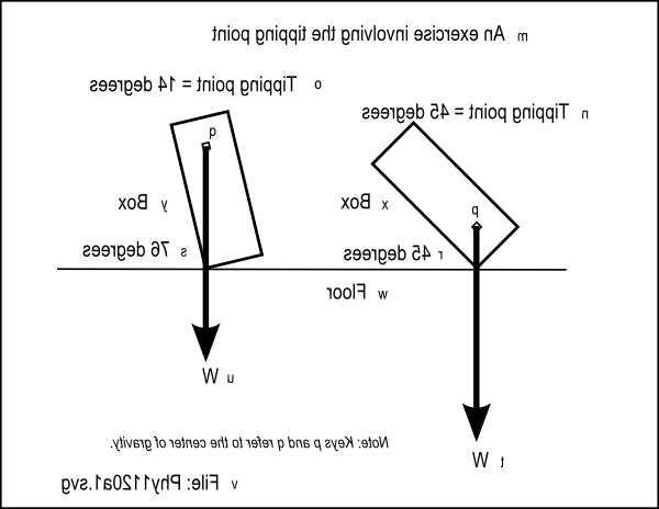 |
Figure 2 shows a non-mirror-image version of the same image.
| Figure 2 . Non-mirror-image version of the image from the file named Phy1120a1.svg. |
|---|
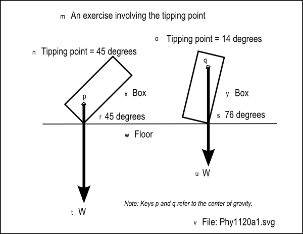 |
Figure 3 shows the key-value pairs that go with the image in the file named Phy1120a1.svg.
| Figure 3 . Key-value pairs for the image in the file named Phy1120a1.svg. |
|---|
m: An exercise involving the tipping point
n: Tipping point = 45 degreeso: Tipping point = 14 degrees
p: Center of gravityq: Center of gravity
r: 45 degreess: 76 degrees
t: Wu: W
v: File: Phy1120a1.svgw: Floor
x: Boxy: Box |
Mark the C.G. of each box
Getting back to your drawing, assume that the C.G. of the left box is one foot up from the bottom and the C.G. of the right box is one foot down from the top (4 feet up from the bottom).In both cases, the C.G. is at the horizontal center of the box. Insert a pin at the location of the C.G. for both boxes and label it C.G. in both cases.
The weight of each box
The downward force that is the weight of each box is on a vertical line that goes through the C.G. and the total weight appears to be concentrated at theC.G. Therefore, when the box is setting flat on the floor, the weight vector for each box is on a line that is 1 ft. from either side of the box.
Vertical weight vectors
Begin at the C.G. for each box and draw a vertical line that extends 7 units down from the C.G. for each box. Label each line as W. These are weight vectors.
Both boxes are in equilibrium
We know from experience that both of these boxes are in equilibrium. We have also just learned that so long as the vertical weight vector that goes through the C.G. alsogoes through the two-foot wide supporting base of the box, the box will be in stable equilibrium.
What is the tipping point?
Label the bottom-right corner of each box as b. Pretend that you drive a nailimmediately to the right of point b and allow it to protrude up from the floor so that when you push on the top-left corner of the box, it will rotate aroundpoint b instead of sliding to the right.
How far can we tip each box in a clockwise direction around the bottom right corner before we lose equilibrium?
Tactile graphics
The file named Phy1120b1.svg contains an image that shows the triangles discussed below .
Figure 4 shows the mirror image that is contained in that file for the benefit of your assistant who will create the tactile graphicfor this exercise.
| Figure 4 . Mirror image from the file named Phy1120b1.svg. |
|---|
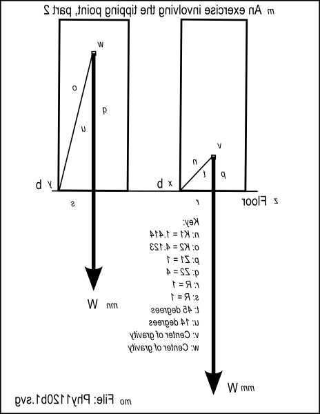 |
Figure 5 shows a non-mirror-image version of the same image.
| Figure 5 . Non-mirror-image version of the image from the file named Phy1120b1.svg. |
|---|
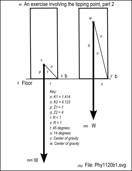 |
Figure 6 shows the key-value pairs that go with the image in the file named Phy1120b1.svg.
Notification Switch
Would you like to follow the 'Accessible physics concepts for blind students' conversation and receive update notifications?

|
|

|
|

|
|

|
|

|
|

|
|

|
|

|
|

|
|

|