

| << Chapter < Page | Chapter >> Page > |
You will be making heavy use of your graph board in this module. In order to make the instructions less awkward, I am going to begin using drawing syntaxwhen talking about the graph board. For example, when I say draw a line from 3,5 to 10,15, that will mean for you to insert a pin at coordinates x=3 and y=5, to insert a second pin at x=10 and y=15, andto connect the two pins with a rubber band, a pipe cleaner, a wire, a piece of yarn, or whatever works for you.
Force is a vector. It has both magnitude and direction. You learned in an earlier module that you can resolve vectors two at a time using a method thatinvolves parallelograms.
Stated more formally, any two forces meeting at a point can be replaced by a single resultant force, which is represented by the diagonal of a parallelogramwhose two adjacent sides represent the two forces.
Tactile graphics
The file named Phy1100b1.svg contains an image from which your assistant can create a tactile graphic to illustrate the scenario described below .
Figure 4 shows the mirror image that is contained in that file for the benefit of your assistant who will create the tactile graphicfor this exercise.
| Figure 4 . Mirror image contained in the file named Phy1100b1.svg. |
|---|
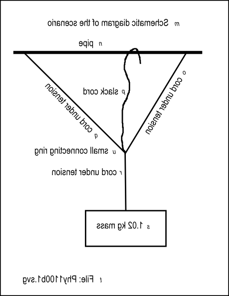 |
Figure 5 shows a non-mirror-image version of the same image.
| Figure 5 . Non-mirror-image version of the image from the file named Phy1100b1.svg. |
|---|
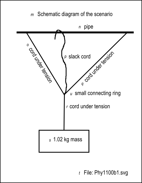 |
Figure 6 shows the key-value pairs that go with the image in the file named Phy1100b1.svg.
| Figure 6 . Key-value pairs for the image in the file named Phy1100b1.svg. |
|---|
m: Schematic diagram of the scenario
n: pipeo: cord under tension
p: slack cordq: cord under tension
r: cord under tensions: 1.02 kg mass
t: File: Phy1100b1.svgu: small connecting ring |
The scenario
Please draw a schematic diagram of this scenario on your graph board.
A strong pipe extends from left to right in the work area supported on both ends. You can get your hands around the pipe to attach things to it.
Light, strong, flexible cords
You tie two light, strong, flexible cords to the pipe approximately one meter apart. (the distance isn't critical). We will ignore the weight of the cords.You thread the ends of the two cords through a small ring that is just large enough for you to tie four cords onto the ring. (The only purpose of the ring is toprovide a convenient way to attach cords together at a single point.)
Adjust the position of the ring
You adjust the position of the ring on each of the cords so that the cord on the left forms a 60-degree south of east angle with the pipe and the cord on theright forms a 45 degree south of west angle with the pipe. Then you tie both cords to the ring at that point.
A triangle
When you pull straight down on the ring, the two cords and the pipe form a triangle. The interior angle at the upper-left vertex is 60 degrees, theinterior angle at the upper-right vertex is 45 degrees, and because the sum of the angles in a triangle is 180 degrees, the interior angle at the bottom vertex is 75degrees.
Notification Switch
Would you like to follow the 'Accessible physics concepts for blind students' conversation and receive update notifications?

|
|

|
|

|
|

|
|

|
|

|
|

|
|

|
|

|
|

|