

| << Chapter < Page | Chapter >> Page > |
See first that the design is wise and just: that ascertained, pursue it resolutely; do not for one repulse forego the purpose that you resolvedto effect.
— William Shakespeare
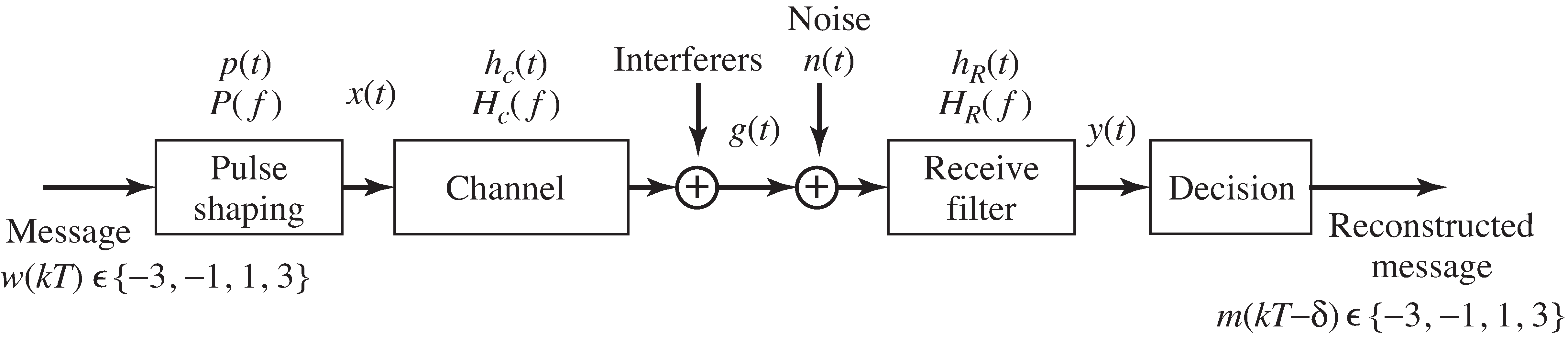
When the message is digital, it must be converted into an analog signal in order to be transmitted.This conversion is done by the “transmit” or “pulse-shaping” filter,which changes each symbol in the digital message into a suitable analog pulse.After transmission, the “receive” filter assists in recapturing the digital values from the received pulses.This chapter focuses on the design and specification of these filters.
The symbols in the digital input sequence are chosen from a finite set of values.For instance, they might be binary , or they may take values from a larger set such as the four-levelalphabet , . As suggested in [link] , the sequence is indexed by the integer , and the data rate is one symbol every seconds. Similarly, the output assumes values from the same alphabet as and at the same rate. Thus the message is fully specified at times for all integers . But what happens between these times, between and ? The analog modulation of Chapter [link] operates continuously, and some values must be used to fill in the digital input between the samples.This is the job of the pulse shaping filter: to turn a discrete-time sequence into an analog signal.
Each symbol of the message initiates an analog pulse that is scaled by the value of the signal.The pulse progresses through the communications system, andif all goes well, the output (after the decision) should be the same as the input, although perhaps with some delay.If the analog pulse is wider than the time between adjacent symbols, the outputsfrom adjacent symbols may overlap, a problem called intersymbol interference , which is abbreviated ISI.A series of examples in "Intersymbol Interference" shows how this happens, and the eye diagram is usedin "Eye Diagrams" to help visualize the impact of ISI.
What kinds of pulses minimize the ISI? One possibility is to choose a shape that isone at time and zero at for all . Then the analog waveform at time contains only the value from the desired input symbol, and no interference fromother nearby input symbols. These are called Nyquist pulses in "Nyquist Pulses" . Yes, this is the same fellow who brought us the Nyquist sampling theoremand the Nyquist frequency.
Besides choosing the pulse shape, it is also necessary to choose a receive filter that helps decode the pulses.The received signal can be thought of as containing two parts:one part is due to the transmitted signal and the other part is due to the noise.The ratio of the powers of these two parts is a kind of signal-to-noise ratio that canbe maximized by choice of the pulse shape. This is discussed in "Matched Filtering" . The chapter concludes in "Matched Transmit and Receive Filters" by considering pulse shaping and receive filters that do both: provide a Nyquist pulse andmaximize the signal-to-noise ratio.
Notification Switch
Would you like to follow the 'Software receiver design' conversation and receive update notifications?

|
|

|
|

|
|

|
|

|
|

|
|

|
|

|
|

|
|

|