

| << Chapter < Page | Chapter >> Page > |
An NFC system consists of a passive network (the card/circuit with information) and an active circuit. We must also take into account the environment surrounding the device. A working knowledge of these three componenents is essential to understanding the inner mechanics of near field communication.
The active circuit has a transmitting antenna that broadcasts RF waves and a number of electrodes that read values corresponding to how the environment reacts to the RF waves. All the processing power is centered in this active circuit and that is where the decoding will take place. This would be considered the reader in the traditional sense. In the following mathematical discussion, the electrode voltages of the active circuit will be values in a vector v1.
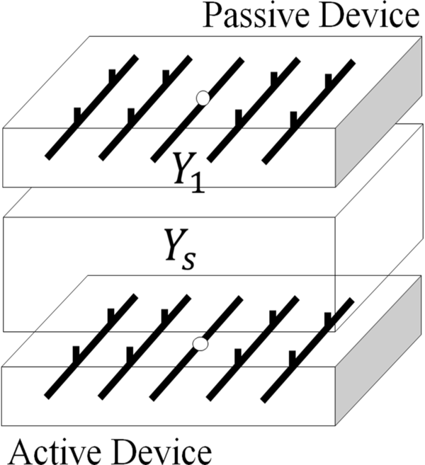
The passive network consists of a series of electrodes which are attached to impedances with values of infinity or zero (open/closed switches). This network might be located inside a phone or other device and is associated with the client side identification. The configuration of the passive network uniquely identifies the user, and thus, our problem becomes one of reverse engineering in which we try to determine the impedances. In our analysis, the passive network voltages are stored in the vector v1 and the impedances are represented by the matrix Y1. Since we are assuming no mutual impedances, this is a diagonal matrix. Rather than using infinity, we have represented the open switches with the very high impedance value of 10,000 ohms.
The “evil channel” is our environment. It converts our beautiful binary impedances into ugly complex voltages. It is our job to understand its effects and make sure that our output is decipherable. The channel matrix we used was given to us and was measured experimentally. It can be modeled by a large square matrix which is of size N x N where N is the total number of voltages (in this case 41). The matrix is labeled Ys and is divided into 9 separate matrices, each representing the mutual interaction of different elements in our matrix.

For example, the elements in matrix W12 would reperesent how the electrodes with voltages v1 interact with the electrodes with voltages v2. Consequently, our answer lies in simplifying this matrix and trying to nullify it’s effect on the input (the Y1 matrix).
As previously stated, the relationship between input impedences and output voltages is non-linear by nature. Thus, our task will be to find some underlying patterns between input and output so that we may adequately decode the voltage values. When presented with a problem as open-ended as this, a number of techniques can be employed. We must make a preliminary analysis of the data through the use of well-constructed plots and principle component analysis.
Notification Switch
Would you like to follow the 'Near field communication simulation & Identification' conversation and receive update notifications?

|
|
|
|
|

|
|

|
|

|
|

|
|

|
|

|
|

|
|

|