<< Chapter < Page Chapter >> Page >
Displaying the Detected DTMF Digits

Real time implementation

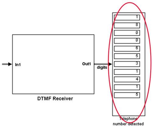
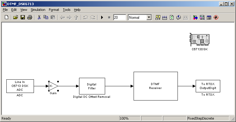
The real-time implementation environment is shown in Figure 7. The DTMF generation will be performed in MATLAB® and sent to the DSK through the PC sound card. The detected digits will be reported through RTDX. A graphic user interface (GUI) will be built to activate the transmitter, and display the reported digits.

Real Time Implementation

The DTMF receiver will be based on the DTMF receiver from the simulation model, with the following changes:

  • Samples will be read from the Analog to Digital Converter, and filtered by a DC removal block This block is necessary to convert the unipolar format of the samples to a 2’s complement format for processing by the DSP.
  • Digits will be reported through RTDX.
  • Addition of the DSK6713 target preference

The dtmf receiver

  • Open the simulation model “DTMF.mdl”, remove all the blocks besides the DTMF receiver block.
  • Open the Simulink ® library browser and add the "C6713DSK".
The C6713DSK target Block
  • Add the “Analog to Digital”” converter (ADC) to your model:
The ADC target Block
The ADC Block Configuration
  • The “TO RTDX” will be used to report the detected digits to the PC. Add it to your model:
The "To RTDX" Block
The "To RTDX" Block Configuration
  • Add the “Digital Filter” and “Gain” blocks for DC removal:
The Digital Filter Block
The Digital Filter Block Configuration
The Gain Block
The Gain Block Configuration
  • The DTMF receiver model is shown Figure 17:
DTMF Receiver
  • Save the model as "DTMF_DSK6713.mdl".
  • Built the model.

The user interface

Functionality

The GUI will perform the following functions:

  • Initialization: Initialize the RTDX interface and loading the DTMF Receiver program we have built in the last section to the DSK.
  • Generate the DTMF signal samples: The GUI will enable the user to select a sequence of 11 digits If the user selects less than 11 digits, the sequence is padded with DTMF digit '1'. to be transmitted. It will create the samples of the DTMF signal based on this selection, and send them to the sound card.
  • Display the detected digits reported by the DSK

Description

The desired GUI is shown in Figure 18

DTMF GUI

It will enable the user to:

  • Dial the digits: every digit dialed is added to a specific buffer, and displayed under the “Dialed Digits” label.
  • Delete the last digit
  • Clear all the digits
  • Send: Create the DTMF signal from the digits selected The DSK operates with a buffer of 11 digits so if the user dialed less then 11 digits we are padding them to 11 in the MATLAB. . A dual-tone signal will be created for each digit. Silence will be inserted between consecutive digits. This signal is sent to the sound blaster using the “sound” command in MATLAB.
  • Display: Digits reported by the DSK will be displayed under the “Detected Digits” label.

The procedure

  • Activate the GUIDE (Graphic User Interface Integrated Development Environment in MATLAB.
  • Open a new GUI and name it DTMF
  • Add 12 Push buttons for the keypad and set their String property to the proper values (0-9,*,#) using the property inspector.
  • Add the Send, Clear and Delete buttons
  • Add 2 Edit Texts objects for display
  • You may now add the labels (static texts):
    • “Dialed Digits”
    • “Detected Estimation”
    • “DTMF Transmitter”
  • Press the “play” button to open the MATLAB script. Name the script “DTMF.m”.
  • Enter the Initialization (DTMF_OpeningFcn ) as shown:

Get Jobilize Job Search Mobile App in your pocket Now!

Get it on Google Play Download on the App Store Now


Source:  OpenStax, From matlab and simulink to real-time with ti dsp's. OpenStax CNX. Jun 08, 2009 Download for free at http://cnx.org/content/col10713/1.1
Google Play and the Google Play logo are trademarks of Google Inc.

Notification Switch

Would you like to follow the 'From matlab and simulink to real-time with ti dsp's' conversation and receive update notifications?

Ask