

| << Chapter < Page | Chapter >> Page > |
To generate the received signal, the Transmitter is called by
[r, s]=BigTransmitter(m, frameParams... ..., rfParams, chanParams);
where
m is the message (or messages, in the case of multiple users) to be transmitted,
frameParams is a structure containing the parameters relating to the frame structure,
rfParams contains the analog/RF related parameters, and
chanParams contains the channel parameters. There are two output arguments:
r is the received sampled signal and
s is the 4-PAM symbols which were transmitted.
Thus, the length of
s is approximately equal to the length of
r times the effective oversampling factor.
In order to control all these features of the , a number of parameters are needed, as summarized in [link] .
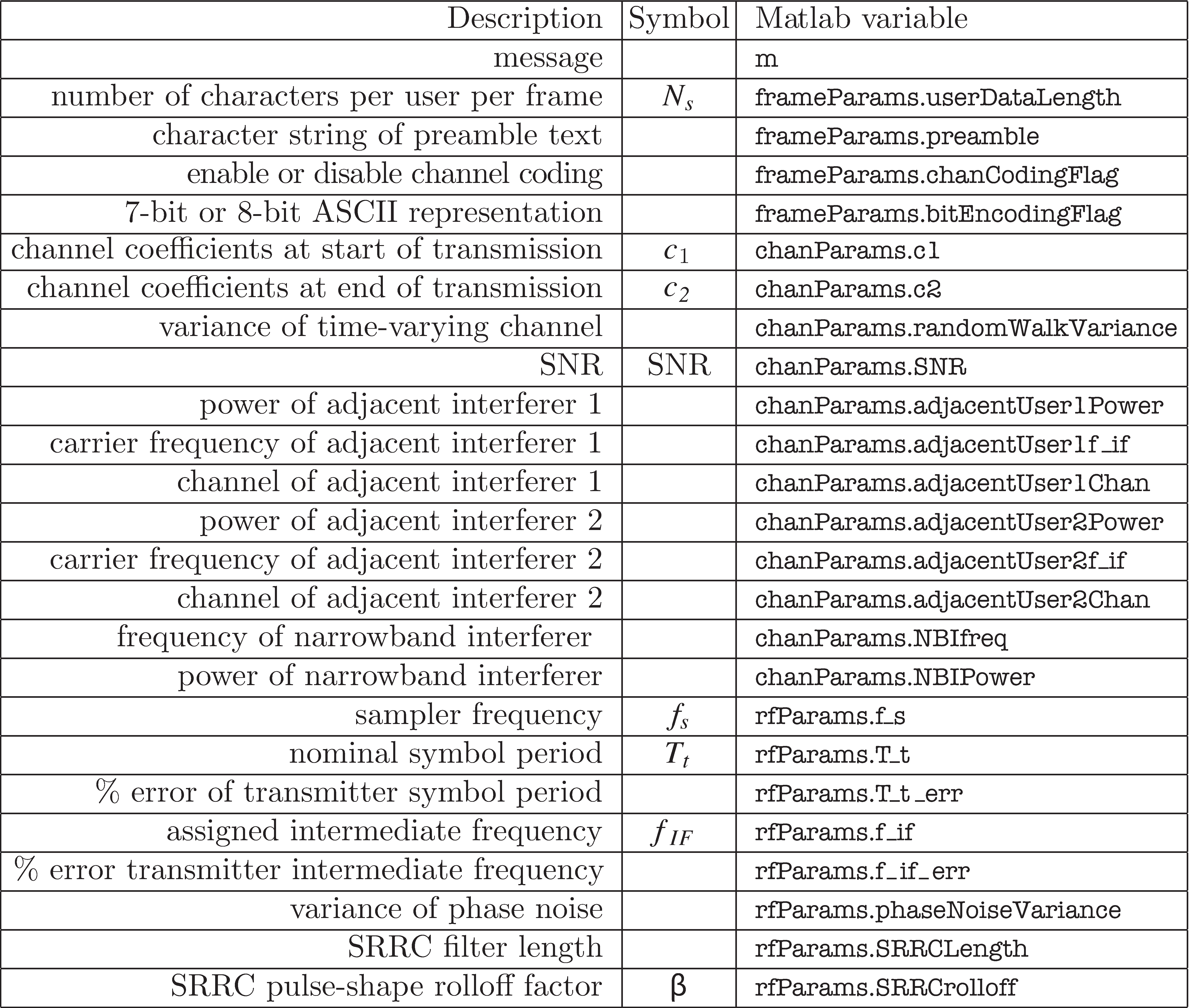
A more detailed description of the parameters follows:
m : A character string matrix, with dimensions equal to the number of users by the message length, containing the ASCII messages to be transmitted. If there is only a single user, this is a single string (row vector).frameParams.userDataLength : The number of text characters per user per frame which (together with
frameParams.preamble ) effectively determines the length of a frame. See
[link] .frameParams.preamble : A character string (i.e. a row vector) containing the preamble text which is presumed known at all receivers.frameParams.chanCodingFlag :
This parameter can be set to either 0 or 1. If set to 0, thetransmitter sends uncoded bits. If set to 1, the transmitter
encodes the data using the binary block (5,2) channel code described in
[link] .frameParams.bitEncodingFlag :
This parameter can be set to either 0 or 1, and controls how thetransmitter translates text into bits. If set to 0, the transmitter
uses an 8-bit representation of the ASCII code, and employs
letters2pam.m . If set to 1, the transmitter uses the 7-bit
representation of the ASCII code, and employs
text2bin.m . See
Examples
[link] and
[link] for details.chanParams.c1 : The impulse response of the time-varying channel at the start of the transmission is specified as a row vector.chanParams.c2 : The impulse response of the time-varying channel at the end of the transmission is also a row vector. The actual channel varies linearly over the course of the transmission from the impulse response in
chanParams.c1 to that in
chanParams.c2 . Hence, if
chanParams.c1 =
chanParams.c2 and
chanParams.randomWalkVariance =0, the channel will be time invariant.chanParams.randomWalkVariance : In addition being able to control the evolution of the channel using
chanParams.c1 and
chanParams.c2 , this parameter specifies a random variation in the channel taps using a random walk. The parameter controls the variance of the random walk process.chanParams.SNR : The signal to noise ratio of the signal. Note that it only controls the amount of AWGN present in the band of the transmitted signal.chanParams.adjacentUser1Power : The relative power of the interference
caused by the first adjacent user, specified in dB. Thus, when set to 0 dB the interferer will have the same power as the transmitter. When set to -Inf, the interferer is effectively disabled.chanParams.adjacentUser1f_if : The carrier frequency of the first interfering user after conversion to IF.chanParams.adjacentUser1Chan : The time-invariant channel of the first interfering user.chanParams.adjacentUser2Power : The relative power of the second interfering user, specified in dB.chanParams.adjacentUser2f_if : The carrier frequency of the second interfering user after conversion to IF.chanParams.adjacentUser2Chan : The time-invariant channel of the second interfering user.chanParams.NBIfreq : The frequency of a narrowband inteferer, after conversion to IF.chanParams.NBIPower : The relative power of the narrowband interferer, specified in dB.rfParams.f_s : The sampler frequency.rfParams.T_t : The nominal (i.e. expected) symbol period.rfParams.T_t_err : The percent error in the transmitter's symbol period, which is presumed unknown at the receiver.rfParams.f_if : The assigned IF carrier frequency (or frequencies).rfParams.f_if_err : The percent error in the transmitter's local oscillator, which is presumed unknown at the receiver.rfParams.phaseNoiseVariance : The variance of the additive noise used to model phase noise in the transmitter.rfParams.SRRCLength : The length of the square-root raised cosine filter.rfParams.SRRCrolloff : The rolloff factor of the square-root raised cosine filter.BigTransmitter.m CodeWhile the
Transmitter is a bit more sophisticated than the simple communications systems of
[link] , it still consists of the same basic operations. This section provides a high-level outline of the code in
BigTransmitter.m , which can be compared with
idsys.m of
[link] .
Peeking inside the
Transmitter code, you will find many familiar operations. In addition, acquainting yourself with the inner workings of code will help prepare you for the receiver design challenges that await. Line numbers of
BigTransmitter.m are indicated in parentheses:
[link] shows a typical received signal and its spectrum as generated by
. The desired message is centered at 10 MHz and has a 1 MHz absolute bandwidth. As seen in the figure, there is an interfering adjacent user centered at baseband with a 1 MHz absolute bandwidth. Assume that the desired user's signal was transmitted at an RF frequency of
MHz and that the local oscillator shown in
[link] operates at
MHz. Assume the Preselect and IF filters are ideal bandpass filters from
MHz and
MHz respectively. Use the transmitter script in
BigEx2.m to generate a received signal identical to
[link] . Note that three parameters have been left incomplete, as indicated by the question marks in
BigEx2.m . Determine the IF frequencies of the desired user and adjacent interfering user, and the sampling frequency
in order to generate the signal in
[link] . Plot the spectrum of the signal you generate.
![Magnitude Spectra of Received Signal r[l]](/ocw/mirror/col11510_1.3_complete/m45992/appHfigure7.png)
The script in
BigEx3.m generates an ideal received signal much like
idsys.m from Chapter
[link] . This time, however, the transmitter sends signals for two users using TDMA, where
frameParams.userDataLength=5 . Mimic the receiver code in
BigIdeal.m to accurately decode the signal for each user. Write your receiver code so that it stores the message for the first user in a variable called
decoded1 , and the message for the second user in a variable called
decoded2 .
In experimenting with the Transmitter, you may find that it will be very useful to look closely at intermediate signals the are inside the transmitter function. There are a variety of ways this can be accomplished. Some possibilities are:
Tx_tdma so that the variables are available in the
M
atlab workspace.Notification Switch
Would you like to follow the 'Software receiver design' conversation and receive update notifications?

|
|

|
|

|
|

|
|

|
|

|
|

|
|
|
|
|

|
|

|