One of the oldest mechanisms is the lever. Stone Age people used them to move large objects.
A lever can be described as a long rigid object with a pivot point somewhere along its length. The pivot is a fixed point about which the lever rotates. The pivot is also known as the fulcrum. Levers are used to do two things: they can move a large load with only a little effort, or they can increase or amplify movement. A seesaw is a simple example of a lever.
Class 1 lever
This lever type is like a seesaw, which has a fixed pivot in the centre of the lever.
Give another example:
Class 2 lever
This lever type has the output between the input and the pivot. A wheelbarrow is an example.
Give another example:
Class 3 lever
This lever type has the input between the pivot and the output. A tweezers is an example of this type of lever.
Give another example:
Linkages
Linkages are levers that link up to other levers, wheels, connecting rods, flywheels etc. They can change the direction of a movement, the size of a force, or make things move in a particular way. The samples illustrate different linkages. You can easily construct them using cardboard, scissors, paper fasteners and drawing pins and test the effect of each linkage.
Push/pull link
This is a linkage useful for changing direction.
Give another example:
Wiper blades
This linkage allows the input link to move parallel to the support frame, like a car windscreen wiper.
Give another example:
Waving arm
The connecting rod is moved by the wheel, which moves the arm.
Give an example:
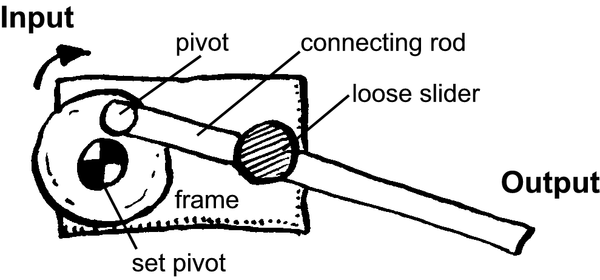
Slider
The wheel turns the connecting rod, which moves through the slider.
Give another example:
LO 2.3
Mechanical Advantage
We use levers every day because they make it is easier to get work done. They give us mechanical advantage (MA) which means that you can move a large load using a small effort.
The MA in the example below is found by comparing the weight of the load with the effort needed to move it. (Remember 1kg = 10 Newton)
Velocity Ratio
If you look at wheelbarrow example again you will see that the distance the effort has to move is much further that that of the load. By comparing the two distances you get the velocity ratio (VR).
Efficiency
Mechanisms are not always 100% efficient due to factors such as parts that bend, friction etc.
In everyday terms, the formula will be:
The scientific formula for the calculation of the efficiency of a mechanism is as follows:
Moments
If a seesaw is not moving but remains level, it is said to be balanced. The forces on either side of the fulcrum are equal and opposite. If the force on one end of the seesaw is greater than the other, or if the fulcrum is not in the centre, then the seesaw will rotate around the fulcrum. This turning force is known as a
moment .
Moments can be used to work out unknown weights or distances of movement. The figure below shows how to calculate the moment for a very large spanner.
Activity 1
Use a simple sketch to help explain the principle of moments.
Write down in your own words the formula to calculate moment (read it from the illustration):
Moment =
If a man weighing 560 N is sitting 3 metres from the pivot of a seesaw, how far from the pivot must a man weighing 700 N sit to create a state of equilibrium (balance)?
Calculate the mechanical advantage of the lever shown in the illustration.
What is the velocity ratio of the lever shown in the figure?
Work out the efficiency of the lifting system in the illustration. It was found that an effort of 50N moving 8m could lift a load of 80N through a distance of 4 m.
LO 2.3
Assessment
LO 2
TECHNOLOGICAL KNOWLEDGE AND UNDERSTANDING The learner will be able to understand and apply relevant technological knowledge ethically and responsibly.
We know this when the learner:
systems and control:2.3 demonstrates knowledge and understanding of interacting mechanical systems and sub-systems by practical analysis and represents them using system diagrams:
gear systems;
belt drive pulley systems with more than one stage;
mechanical control mechanism (e.g. ratchet and pawl, cleats);
pneumatic or hydraulic systems that use restrictors;
one-way valves;
systems where mechanical, electrical or pneumatic or hydraulic systems are combined;