

| << Chapter < Page | Chapter >> Page > |
The channel may be near ideal (i.e., a unit gain multisymbol delay) or it may have significant intersymbol interference.In either case, the impulse response of the channel is unknown at the receiver, though an upper bound on itsdelay spread may be available. There are also disturbances that may occur during thetransmission. These may be wideband noise with flat power spectral density or they may be narrowband interferers, or both.They are unknown at the receiver.
The achieved intermediate frequency is required to be within percent of its assigned value. The carrier phase is unknown to the receiver and may vary over time, albeit slowly.This means that the phase of the intermediate frequency signal presented to the receiver sampler may also vary.
The bandpass filter before the downconverter in the front-end of the receiver in [link] partially attenuates adjacent 204 kHz wide FDM user bands. The automatic gain control is presumed locked and fixedover each transmission. The free-running sampler frequency of 850 kHz is well abovetwice the 102 kHz baseband bandwidth of the user of interest. This is necessary for the baseband analog signal interpolatorused in the timer in the DSP portion of the receiver in [link] . However, the sampler frequency is not abovetwice the highest frequency of the IF signal. This means that the sampled received signal has replicated thespectrum at the output of the front-end analog downconverter lowpass filter to frequencies between zero and IF.
| Symbol source alphabet | , |
| Assigned intermediate frequency | 2 MHz |
| Nominal symbol period | 6.4 microseconds |
| SRRC pulse shape rolloff factor | |
| FDM user slot allotment | 204 kHz |
| Width of SRRC pulse shape | 8 clock periods |
| Frame marker/training sequence | See [link] |
| Frame marker sequence period | 1120 symbols |
| Time-varying IF carrier phase | Filtered white noise |
| IF offset | Fixed, % |
| Timing offset | Fixed |
| Symbol period offset | Fixed, % |
| Intersymbol interference | Max. delay spread |
| = 7 symbols | |
| Sampler frequency | 850 kHz |
Before describing the specific design requirements that must be metby a successful receiver, this section makes some generic remarks about a systematic approach toreceiver design. There are four generic stages:
While it may seem as though each stage requires that choices made in the preceding stages be fixed, in reality, difficulties encountered at one stage in the design processmay require a return to (and different choices to be made in) earlier stages.As will soon become clear, the problem specification has basically (pre)resolved thedesign issues of the first two stages.
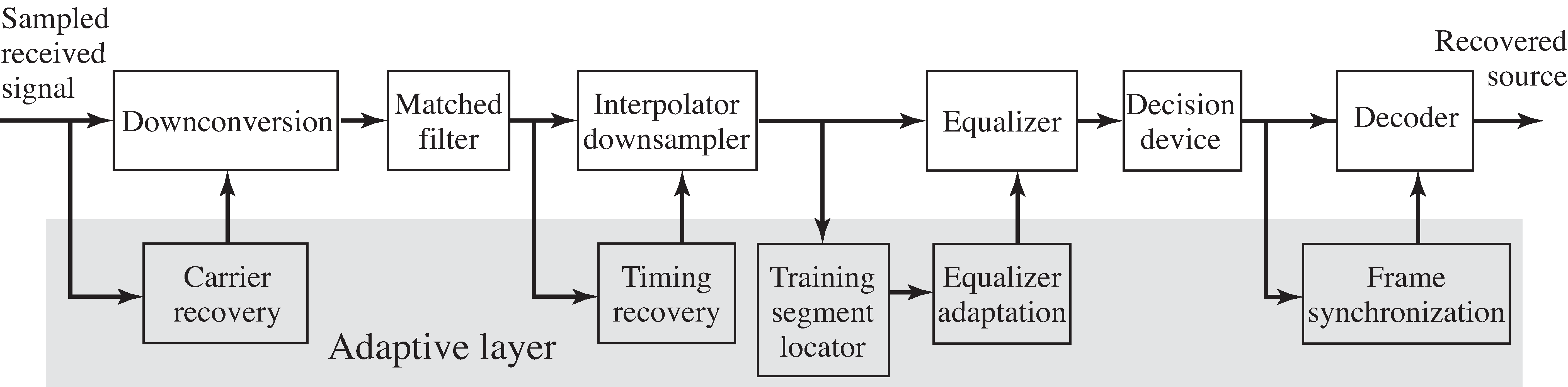
The first stage is to select the basic components and the order in which they occur.The design layout first established in [link] (and reappearing in the schematic of the DSP portion of the receiver in [link] ) suggests one feasible structure. As the signal enters the receiver it is downconverted(with carrier recovery), matched filtered, interpolated (with timing recovery), equalized (adaptively),quantized, and decoded (with frame synchronization). This classical ordering, while popular, is not theonly (nor necessarily the best) way to recover the message from the noisy, ISI-distorted, FDM–PAM–IF received signal.However, it offers a useful foundation for assessing the relative benefits and costs of alternativereceiver configurations. Also, we know for sure that the receiver can be built this way. Other configurations may work, but we have not testedthem. If this sounds like a challenge, rest assured it is. Research continues worldwide, making compilation of acomplete handbook of receiver designs and algorithms a Sisyphean task. The creation of “new” algorithms with minor variations thatexploit a particular application-specific circumstance is a popular pastime of communication engineers.Perhaps you too will come up with a unique approach!
Notification Switch
Would you like to follow the 'Software receiver design' conversation and receive update notifications?

|
|

|
|

|
|

|
|

|
|

|
|

|
|

|
|

|
|

|