

| << Chapter < Page | Chapter >> Page > |
and illustrated in [link] For N odd, the ideal infinitely and shifted filter coefficients are the inverse DTFT of this amplitude given by
with the indeterminate . This is now truncated and shifted by to give the optimal, causal length- FIR filter coefficients as
and otherwise. The corresponding derivation for an even length starts with the inverseDTFT for a shifted even length filter in Equation 15 from Chebyshev or Equal Ripple Error Approximation Filters and after shifting by gives the same result as [link] .
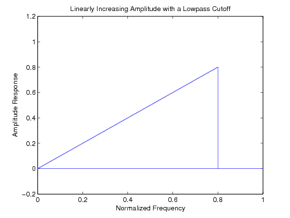
Fortunately the inverse DTFT for an ideal differentiator combined with a lowpass filter can also be analytically evaluated. The ideal amplituderesponse is the same as [link] and [link] but, since this case has an odd symmetric impulse response, the inverse DTFT uses sine functions which forodd gives
with the indeterminate . This is now truncated and shifted by to give the optimal, causal length- FIR filter coefficients as
and otherwise. Again the corresponding derivation for an even length gives the sameresult as in [link] . Note this very general single formula includes as special cases the odd and even length full band ( ) differentiator given in [link] . Also note that for a full band differentiator, an even length is much preferred because of the zero at for an odd length. However, for the differentiator with a lowpass filter, the zero aids in the lowpass filtering and, therefore,might be an advantage.
The inverse DTFT for an ideal Hilbert transform [link] combined with a lowpass filter can also be analytically evaluated. The ideal amplituderesponse is the same as [link] but with a constant phase shift of . Since this case has an odd symmetric impulse response, the inverse DTFT uses sine functions which for odd which gives
with the indeterminate . This is now truncated and shifted by to give the optimal, causal length- FIR filter coefficients as
and otherwise. Again the corresponding derivation for an even length gives the same result as in [link] . The ideal amplitude response is shown in [link] .

All of the four lowpass filters described above exhibit the Gibbs phenomenon when truncated to a finite length. To remove this effect andto give a more explicit specification of the pass and stopband edges, a transition band is inserted between the pass and stopband. A transitionfunction can be placed in this band to make the total desired amplitude response a continuous function.
If we use a order spline as the transition function, the effect of adding this transition band to the basic lowpass filter ideal amplitudegiven in [link] is to multiply the ideal impulse response in [link] by a the power of a sinc function to give
Notification Switch
Would you like to follow the 'Digital signal processing and digital filter design (draft)' conversation and receive update notifications?

|
|

|
|

|
|

|
|

|
|

|
|

|
|

|
|

|
|

|