

| << Chapter < Page | Chapter >> Page > |

The results shown in other modules ( circuit elements , KVL and KCL , interconnection laws ) with regard to this circuit , and the values of other currents and voltages in this circuit as well, have profound implications.
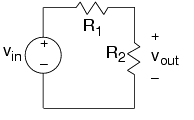
Resistors connected in such a way that current from one must flow only into another—currents in all resistors connected this way have the samemagnitude—are said to be connected in series . For the two series-connected resistors in the example, the voltage across one resistor equals the ratio of that resistor's value and the sum of resistancestimes the voltage across the series combination . This concept is so pervasive it has a name: voltage divider .
The input-output relationship for this system, found in this particular case by voltage divider, takes the formof a ratio of the output voltage to the input voltage. In this way, we express how the components used to build the system affect the input-output relationship. Because thisanalysis was made with ideal circuit elements, we might expect this relation to break down if the input amplitude is too high(Will the circuit survive if the input changes from 1 volt to one million volts?) or if the source's frequency becomes toohigh. In any case, this important way of expressing input-output relationships—as a ratio of output toinput—pervades circuit and system theory.
The current is the current flowing out of the voltage source. Because it equals , we have that :

Thus, the circuit the voltage source "feels" (through the current drawn from it) is a single resistor having resistance . Note that in making this equivalent circuit, the output voltagecan no longer be defined: The output resistor labeled no longer appears. Thus, this equivalence is made strictly from the voltage source's viewpoint.
Notification Switch
Would you like to follow the 'Circuits' conversation and receive update notifications?

|
|

|
|

|
|

|
|

|
|

|
|

|
|

|
|

|
|

|