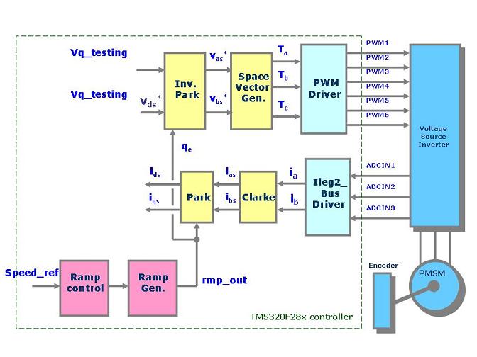
RMPCNTL (ramp control): this module used by the instantiation of the object rc1, structure for which we can access each variable, controls the acceleration and deceleration rate of the speed command speed_ref .This speed command is passed the input of the RMPCNTL module rc1.target_value. The output of this module is called rc1.setpt_value which represents the frequency of the saw-tooth we want to generate.This frequency information is then passed to the ramp generator module.
RAMPGEN (ramp generator): to use this module, we instantiate an object rg1. The input of this module is rg1.rmp_freq . The rotating angle we generate (saw-tooth waveform) is rg1.rmp_out. This angle is then used for the Inverse PARK transformation.
IPARK (Inverse Park Transformation): instance ipark1. Computed rotating angle is passed into the ipark1.ang variable. The d and q inputs to the inverse Park transformation control the command magnitude via the variables ipark1.de and ipark1.qe.
SVGENDQ (Space Vector Generation): instance svgen_dq1. This module takes the output of the IPARK module and calculates the modulation to be applied on the duty cycle of the three pairs of PWM connected to the three phases inverter bridge (svgen_dq1.Ta, svgen_dq1.Tb and svgen_dq1.Tc).
PWMGEN (Pulse Width Modulation Generation driver): this modules is the only one linked to the DSP peripherals. Duty-cycles previously calculated are passed into the DSP PWM registers via the instant pw1. PWMGEN takes care of the DSP PWM initialization (timer set-up, PWM polarity and so on).
Run the
PMS_Motor_data M-file. This file initializes the following variables:
Run the model and double-click the “Stator Current” and “Rotor Speed” scopes.
Stator CurrentRotor Speed
Running the pmsm in open loop
The purpose of this step is to simulate open–loop operation with power-stage and motor connected and to check out current sensing and feedback path.
Open Loop
Key Modules Used for this level
In addition to the modules used in the previous section, we now start to build the feedback loop using:
ILEG2DCBUSMEAS_VCON (current leg and DC bus measurement): This module initializes the ADC to start automatic conversions of channels selected by the user on timer 1 underflow. ADC conversion results are automatically formatted and stored into dedicated variables.
CLARKE (Clarke transform module): This module converts the measured current into CLARKE coordinates in the reference frame (α, β).
PARK (Park Transformation): This module converts the (α, β) coordinates into two DC quantities.
Receive real-time job alerts and never miss the right job again
Source:
OpenStax, From matlab and simulink to real-time with ti dsp's. OpenStax CNX. Jun 08, 2009 Download for free at http://cnx.org/content/col10713/1.1
Google Play and the Google Play logo are trademarks of Google Inc.
Notification Switch
Would you like to follow the 'From matlab and simulink to real-time with ti dsp's' conversation and receive update notifications?