<< Chapter < Page Chapter >> Page >

Check Your Understanding In considering the following schematic and the power supplied and consumed by a circuit, will a voltage source always provide power to the circuit, or can a voltage source consume power?

The figure shows positive terminal of voltage source V subscript 1 of 24 V connected in series to resistor R subscript 1 of 10 kΩ connected in series to positive terminal of voltage source V subscript 2 of 12 V connected in series to resistor R subscript 2 of 30 kΩ.

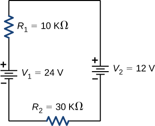
The circuit can be analyzed using Kirchhoff’s loop rule. The first voltage source supplies power: P in = I V 1 = 7.20 mW. The second voltage source consumes power: P out = I V 2 + I 2 R 1 + I 2 R 2 = 7.2 mW .

Got questions? Get instant answers now!

Calculating current by using kirchhoff’s rules

Find the current flowing in the circuit in [link] .

The figure shows positive terminal of voltage source V subscript 2 of 24 V connected in series to resistor R subscript 3 of 20 Ω connected in series to resistor R subscript 1 of 10 Ω connected in series to positive terminal of voltage source V subscript 1 of 12 V connected in series to resistor R subscript 2 of 30 Ω.
This circuit consists of three resistors and two batteries connected in series. Note that the batteries are connected with opposite polarities.

Strategy

This circuit can be analyzed using Kirchhoff’s rules. There is only one loop and no nodes. Choose the direction of current flow. For this example, we will use the clockwise direction from point a to point b . Consider Loop abcda and use [link] to write the loop equation. Note that according to [link] , battery V 1 will be added and battery V 2 will be subtracted.

Solution

Applying the junction rule yields the following three equations. We have one unknown, so one equation is required:

Loop a b c d a : I R 1 V 1 I R 2 + V 2 I R 3 = 0 .

Simplify the equations by placing the unknowns on one side of the equations. Use the values given in the figure.

I ( R 1 + R 2 + R 3 ) = V 2 V 1 . I = V 2 V 1 R 1 + R 2 + R 3 = 24 V 12 V 10.0 Ω + 30.0 Ω + 10.0 Ω = 0.20 A .

Significance

The power dissipated or consumed by the circuit equals the power supplied to the circuit, but notice that the current in the battery V 1 is flowing through the battery from the positive terminal to the negative terminal and consumes power.

P R 1 = I 2 R 1 = 0.40 W P R 2 = I 2 R 2 = 1.20 W P R 3 = I 2 R 3 = 0.80 W P V 1 = I V 1 = 2.40 W P dissipated = 4.80 W P source = I V 2 = 4.80 W

The power supplied equals the power dissipated by the resistors and consumed by the battery V 1 .

Got questions? Get instant answers now!

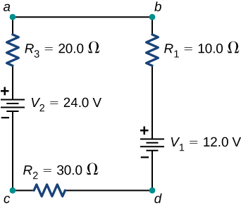
Check Your Understanding When using Kirchhoff’s laws, you need to decide which loops to use and the direction of current flow through each loop. In analyzing the circuit in [link] , the direction of current flow was chosen to be clockwise, from point a to point b . How would the results change if the direction of the current was chosen to be counterclockwise, from point b to point a ?

The current calculated would be equal to I = −0.20 A instead of I = 0.20 A . The sum of the power dissipated and the power consumed would still equal the power supplied.

Got questions? Get instant answers now!

Multiple voltage sources

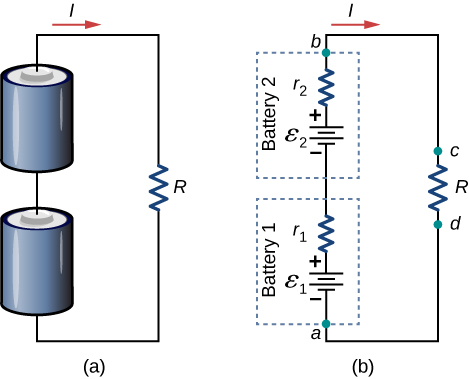
Many devices require more than one battery. Multiple voltage sources, such as batteries, can be connected in series configurations, parallel configurations, or a combination of the two.

In series, the positive terminal of one battery is connected to the negative terminal of another battery. Any number of voltage sources, including batteries, can be connected in series. Two batteries connected in series are shown in [link] . Using Kirchhoff’s loop rule for the circuit in part (b) gives the result

ε 1 I r 1 + ε 2 I r 2 I R = 0 , [ ( ε 1 + ε 2 ) I ( r 1 + r 2 ) ] I R = 0.
Part a shows two batteries connected in series to a resistor. Part b shows the circuit diagram for part a, with each battery represented by an emf source and internal resistance.
(a) Two batteries connected in series with a load resistor. (b) The circuit diagram of the two batteries and the load resistor, with each battery modeled as an idealized emf source and an internal resistance.
Practice Key Terms 3

Get Jobilize Job Search Mobile App in your pocket Now!

Get it on Google Play Download on the App Store Now


Source:  OpenStax, University physics volume 2. OpenStax CNX. Oct 06, 2016 Download for free at http://cnx.org/content/col12074/1.3
Google Play and the Google Play logo are trademarks of Google Inc.

Notification Switch

Would you like to follow the 'University physics volume 2' conversation and receive update notifications?

Ask