

| << Chapter < Page | Chapter >> Page > |
Communication systems must be robust to the presence of noises and other disturbances that arise in the channel and in the various stages of processing.Matched filtering is aimed at reducing the sensitivity to noise, which can be specified in termsof the power spectral density.
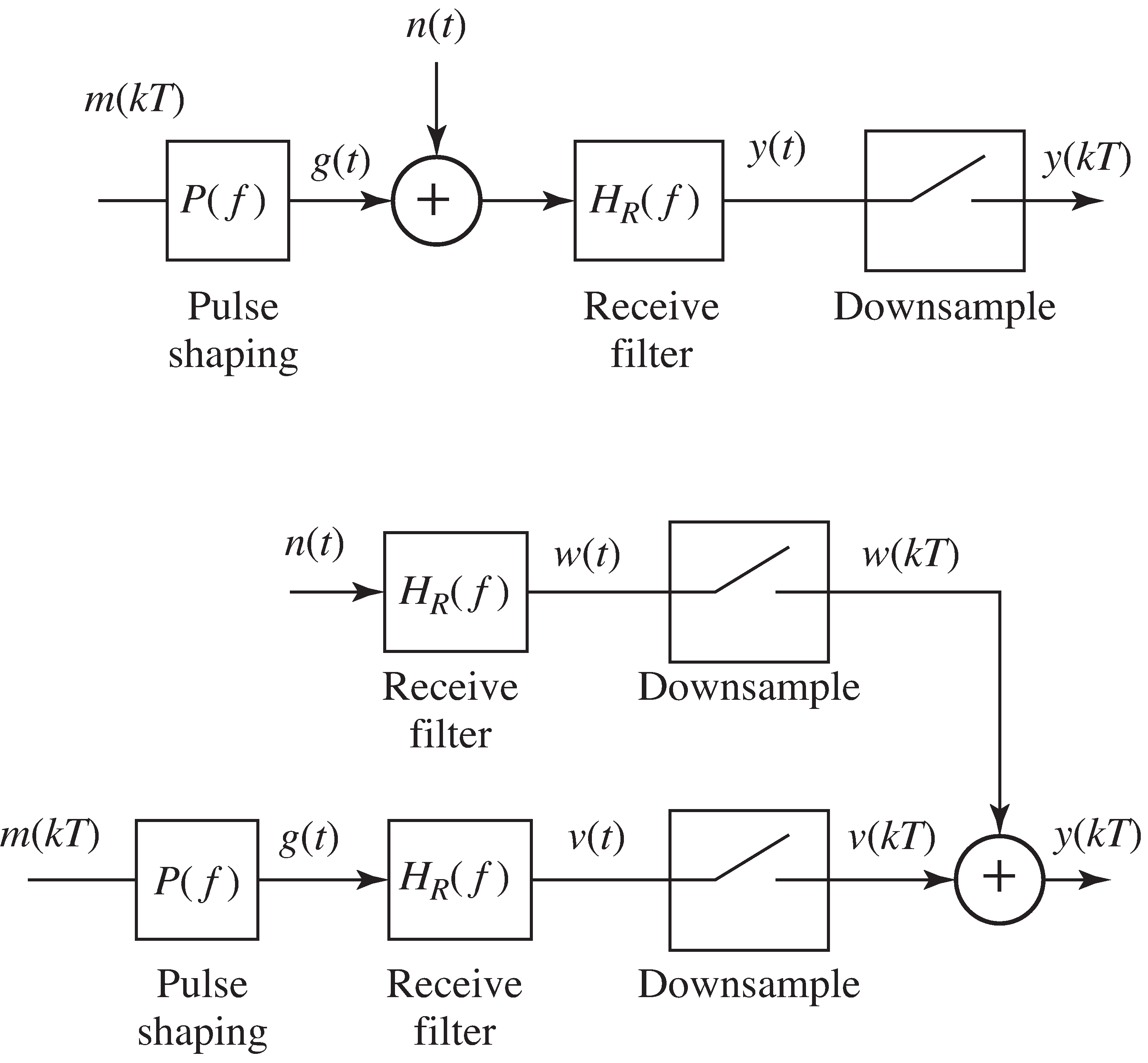
Consider the filtering problem in which a message signal is added to a noise signal and thenboth are passed through a linear filter. This occurs, for instance, when the signal of [link] is the output of the pulse shaping filter (i.e., no interferers are present),the channel is the identity, and there is noise present. Assume that the noise is “white”; that is,assume that its power spectral density is equal to some constant for all frequencies.
The output of the linear filter with impulse response can be described as the superposition of two components,one driven by and the other by ; that is,
where
This is shown in block diagram form in [link] . In both components, the processing and the output signal are the same. The bottom diagram separates outthe component due to the signal ( , which contains the message filtered through the pulse shape and the receive filter),and the component due to the noise ( , which is the noise filtered through the receive filter).The goal of this section is to find the receive filter that maximizes the ratio of the power in thesignal to the power in the noise at the sample instants.
Consider choosing so as to maximize the power of the signal at time compared with the power in (i.e., to maximize relative to the total power of the noise component ). This choice of tends to emphasize the signal and suppress the noise . The argument proceeds by finding the transfer function that corresponds to this .
The total power in is
From the inverse Fourier transform,
where . Thus,
Says that for , . Thus,
The quantity to be maximized can now be described by
Schwarz's inequality [link] says that
and equality occurs only when . This converts [link] to
which is maximized with equality when
must now be transformed to find the corresponding impulse response . Since when , (use the frequency scaling property of Fourier transforms [link] with a scale factor of ),
Applying the time shift property [link] yields
Notification Switch
Would you like to follow the 'Software receiver design' conversation and receive update notifications?

|
|

|
|

|
|

|
|

|
|

|
|
|
|
|

|
|

|
|
|
|