

| << Chapter < Page | Chapter >> Page > |
First, build a front panel as shown in [link] a. For the inputs, consider two Knobs ( Controls → Modern → Numeric → Knob ) . Adjust the size of the knobs by using the Positioning tool. One can modify knob properties such as precision and data type by right-clicking and choosing Properties from the shortcut menu. A Knob Properties dialog box opens and an Appearance tab is shown by default. Edit the label of one of the knobs to read Input 1. Select the Data Type tab, click Representation and select Byte to change the data type from double precision to byte. One can also perform this by right-clicking on the knob and choosing Representation → Byte from the shortcut menu. In the Data Type tab, a default value needs to be specified. In this example, the default value is considered to be 0. The default value can be set by right-clicking on the control and choosing Data Operations → Make Current Value Default from the shortcut menu. Also, this control can be set to a default value by right-clicking and choosing Data Operations → Reinitialize to Default Value from the shortcut menu.
Label the second knob as Input 2 and repeat all the adjustments as carried out for the first knob except for the data representation part. Specify the data type of the second knob to be double precision to demonstrate the difference in the outcome. As the final front panel configuration step, align and distribute the objects using the appropriate buttons on the front panel toolbar.
To set the outputs, locate and place a numeric indicator, a round LED ( Controls → Modern → Boolean → Round LED ) and a gauge ( Controls → Modern → Numeric → Gauge ) . Edit the labels of the indicators as shown in [link] .
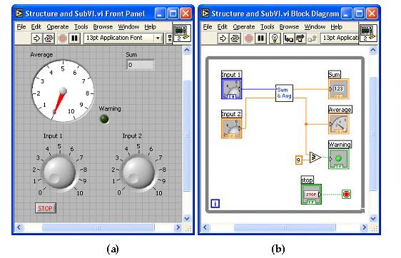
Locate a Greater or Equal? function from Functions → Programming → Comparison → Greater or Equal? to compare the average output of the subVI with a threshold value. Create a wire branch on the wire between the Average terminal of the subVI and its indicator via the Wiring tool. Then, extend this wire to the x terminal of the Greater or Equal? function. Right-click on the y terminal of the Greater or Equal? function and choose Create → Constant to place a numeric constant. Enter 9 in the numeric constant and wire the round LED, labeled as Warning, to the x>=y? terminal of this function to provide a Boolean value.
To run the VI continuously, use a while loop structure. Choose Functions → Programming → Structures → While Loop to create a while loop . Change the size by dragging the mouse to enclose the objects in the while loop , as illustrated in [link] .
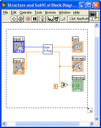
Once this structure is created, its boundary, together with the loop iteration terminal
![]() and conditional terminal
and conditional terminal
![]() , get shown on the block diagram. If one creates the
while loop by using
Functions
→
Programming
→
Structures
→
While Loop , the
Stop button is not included as part of the structure. One can create this button by right-clicking on the conditional terminal and choosing
Create
→
Control from the shortcut menu. It is possible to wire a Boolean condition to a conditional terminal, instead of a
Stop button, to stop the loop programmatically.
, get shown on the block diagram. If one creates the
while loop by using
Functions
→
Programming
→
Structures
→
While Loop , the
Stop button is not included as part of the structure. One can create this button by right-clicking on the conditional terminal and choosing
Create
→
Control from the shortcut menu. It is possible to wire a Boolean condition to a conditional terminal, instead of a
Stop button, to stop the loop programmatically.
Next run the VI to verify its functionality. After clicking the Run button on the toolbar, adjust the knobs to alter the inputs. Verify whether the average and sum are displayed correctly in the gauge and numeric indicators. Note that only integer values can be entered via the Input 1 knob while real values can be entered via the Input 2 knob. This is due to the data types associated with these knobs. The Input 1 knob is set to byte type, in other words, I8 or 8-bit signed integer. As a result, one can enter only integer values within the range -128 and 127. Considering that the minimum and maximum values of this knob are set to 0 and 10, respectively, one can enter only integer values from 0 to 10 for this input.

Use the Probe tool to observe data that are being passed while a VI is running. A probe can be placed on a wire by using the Probe tool or by right-clicking on a wire and choosing Probe from the shortcut menu. Probes can also be placed while a VI is running.
Placing probes on wires creates probe windows through which one can observe intermediate values. As an example of using custom probes, use four probe windows at the probe locations 1 through 4 in the Sum and Average VI to probe the values at those locations. These probes and their locations are illustrated in [link] .

With the Profile tool, one can gather timing and memory usage information. Make sure to stop the VI before selecting Tools → Profile → Performance and Memory to open a Profile window.
Place a checkmark in the Timing Statistics checkbox to display timing statistics of the VI. The Timing Details option offers more detailed VI statistics such as drawing time. To profile memory usage as well as timing, check the Memory Usage checkbox after checking the Profile Memory Usage checkbox. Note that this option can slow down VI execution. Start profiling by clicking the Start button on the profiler, then run the VI. Obtain a snapshot of the profiler information by clicking on the Snapshot button. After viewing the timing information, click the Stop button. The profile statistics can be stored in a text file by clicking the Save button.
An outcome of the profiler is shown in [link] after running the Sum and Average or L1.1 VI. [link] provides more details on the Profile tool.

Build a VI to compute the variance of an array . The variance is defined as:
where denotes the average of the array x. For x, use all the integers from 1 to 1000.
Insert Solution Text Here
Build a VI to check whether a given positive integer is a prime number and display a warning message if it is not a prime number.
Insert Solution Text Here
Build a VI to generate the first prime numbers and store them using an indexing array. Display the outcome.
Insert Solution Text Here
Build a VI to sort integer numbers (positive or negative) in ascending or descending order.
Insert Solution Text Here
Notification Switch
Would you like to follow the 'An interactive approach to signals and systems laboratory' conversation and receive update notifications?

|
|

|
|

|
|

|
|

|
|

|
|

|
|

|
|
|
|
|

|