

| << Chapter < Page | Chapter >> Page > |
The Dual-tone multi-frequency (DTMF) signaling method was developed originally to replace pulse (Dial Pulse or DP in the U.S. ) and loop disconnect (LD) signaling methods to dial numbers, in order to shorten the holding time of the switch during dialing , specially for long distance calls.
DTMF signaling uses two tones to represent each key on the touch pad. There are 12 distinct tones The DTMF method defines four additional digits: “A”, “B”,”C”&“D”. Most of the systems today do not use those digits. (Please refer to Table 1). When any key is pressed the tone of the column and the tone of the row are generated. As an example, pressing the '5' button generates the tones 770 Hz and 1336 Hz. The frequencies were chosen to avoid harmonics: no frequency is a multiple of another, the difference between any two frequencies does not equal any of the frequencies, and the sum of any two frequencies does not equal any of the frequencies.
| . | 1209 Hz | 1336 Hz | 1477 Hz |
| 697 Hz | 1 | 2 | 3 |
| 770 Hz | 4 | 5 | 6 |
| 852 Hz | 7 | 8 | 9 |
| 941 Hz | * | 0 | # |
Table 1- DTMF frequencies
The low frequencies are referred as rows, The higher frequencies are referred as columns.
This example will show the implementation of a DTMF receiver using the DSK6713. The DTMF receiver will be based on the simulation model used in the Simulink demo. A graphic user interface (GUI) will also be created to activate the DSK6713. DTMF digits will be sent from the PC sound card.
Figure 1 shows the model used to simulate DTMF detection and generation.

The DTMF generator is composed by 7 sine wave generators, corresponding to the 7 DTMF frequencies. The oscillators are grouped as described in Table 1. The oscillators’’ outputs are multiplexed and summed (Please refer to Figure 2). Upon selection of a digit to be transmitted, the correspondent oscillators are activated.

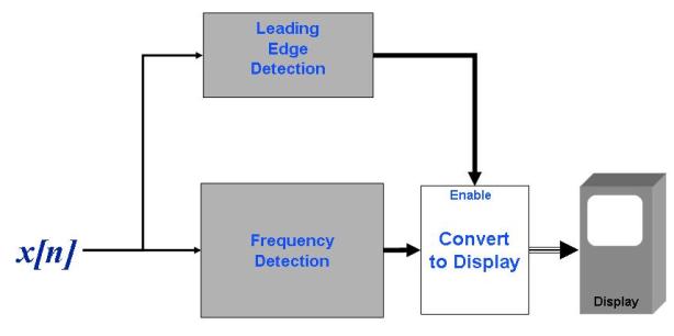
The DTMF detection comprises two processes, the frequency detection algorithm itself, and a leading edge detection subsystem.
The frequency detection subsystem measures the energy present at the seven frequencies, and calculates the digit by taking the component of maximum energy in the lower and upper frequency groups. The process is shown in Figure 3. This process runs continuously; however the calculated digit is reported only if its energy is above a threshold as determined by the leading edge detection subsystem. The DTMF detection process is shown in Figure 4.


Notification Switch
Would you like to follow the 'From matlab and simulink to real-time with ti dsp's' conversation and receive update notifications?

|
|

|
|

|
|

|
|

|
|

|
|

|
|

|
|

|
|

|