

| << Chapter < Page | Chapter >> Page > |
In order to generate a basis system that would allow a higher resolution decomposition at high frequencies, we will iterate (split and down-sample)the highpass wavelet branch of the Mallat algorithm tree as well as the lowpass scaling function branch. Recall that for the discrete wavelettransform we repeatedly split, filter, and decimate the lowpass bands. The resulting three-scale analysis tree (three-stage filter bank) is shown in Figure: Three-Stage Two-Band Analysis Tree . This type of tree results in a logarithmic splitting of the bandwidths and tiling of the time-scale plane, as shown in [link] .
If we split both the lowpass and highpass bands at all stages, the resulting filter bank structure is like a full binary tree as in [link] . It is this full tree that takes calculations and results in a completely evenly spaced frequency resolution. In fact, its structure is somewhat similar to the FFT algorithm.Notice the meaning of the subscripts on the signal spaces. The first integer subscript is the scale of that space as illustrated in [link] . Each following subscript is a zero or one, depending the path taken through the filter bank illustrated in Figure: Three-Stage Two-Band Analysis Tree . A “zero" indicates going through a lowpass filter (scaling functiondecomposition) and a “one" indicates going through a highpass filter (wavelet decomposition). This is different from the convention forthe case in [link] .
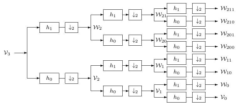
[link] pictorially shows the signal vector space decomposition for the scaling functions and wavelets. [link] shows the frequency response of the packet filter bank much as Figure: Frequency Bands for the Analysis Tree did for and [link] for wavelet systems.
[link] shows the Haar wavelet packets with which we finish the example started in Section: An Example of the haar Wavelet System . This is an informative illustration that shows just what “packetizing" does to the regular wavelet system. Itshould be compared to the example at the end of Chapter: A multiresolution formulation of Wavelet Systems . This is similar to the Walsh-Haddamar decomposition,and [link] shows the full wavelet packet system generated from the Daubechies scaling function. The “prime" indicates this is the Daubechies system with thespectral factorization chosen such that zeros are inside the unit circle and some outside. This gives the maximum symmetry possiblewith a Daubechies system. Notice the three wavelets have increasing “frequency." They are somewhat like windowed sinusoids, hence thename, wavelet packet. Compare the wavelets with the and Daubechies wavelets.
Normally we consider the outputs of each channel or band as the wavelet transform and from this have a nonredundant basis system. If, however,we consider the signals at the output of each band and at each stage or scale simultaneously, we have more outputs than inputs and clearly have aredundant system. From all of these outputs, we can choose an independent subset as a basis. This can be done in an adaptive way, depending on thesignal characteristics according to some optimization criterion. One possibility is the regular wavelet decomposition shown in Figure: Frequency Bands for the Analysis Tree .
Notification Switch
Would you like to follow the 'Wavelets and wavelet transforms' conversation and receive update notifications?

|
|

|
|
|
|

|
|

|
|

|
|

|
|

|
|

|
|

|