

| << Chapter < Page | Chapter >> Page > |
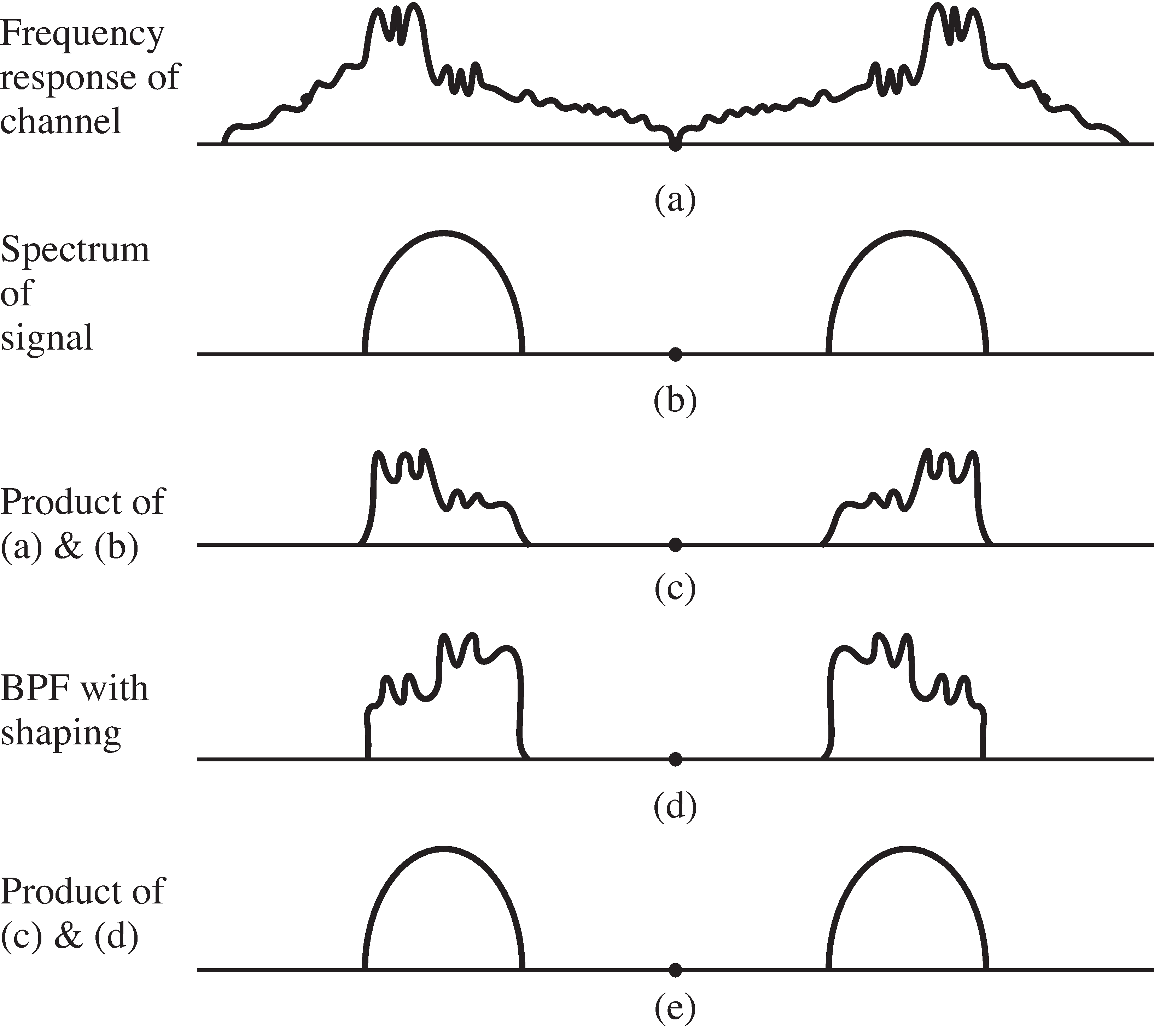
Thus, filtering in the receiver can be used to reshape the received signal within the frequency band of the transmissionas well as to remove unwanted out-of-band frequencies.
Another kind of corruption that a signal may encounter on its journey from the transmitter to the receiver is called“fading,” where the frequency response of the channel changes slowly over time. This may be caused because the transmission pathchanges. For instance, a reflection from a cloud might disappear when the cloud dissipates, an additional reflection mightappear when a truck moves into a narrow city street, or in a mobile device such as a cell phone the operatormight turn a corner and cause a large change in the local geometry of reflections. Fading may also occurwhen the transmitter and/or the receiver are moving. The Doppler effect shifts the frequencies slightly,causing interferences that may slowly change.
Such time-varying problems cannot be fixed by a single fixed filter; rather, the filter must somehow compensatedifferently at different times. This is an ideal application for the adaptive elements of [link] , though results from the study of linear filters will becrucial in understanding how the time variations in the frequency response can be represented as time-varyingcoefficients in the filter that represents the channel.
Linear systems appear in many places in communication systems. The transmission channel is often modeled as a linear systemas in [link] . The bandpass filters used in the front end toremove other users (and to remove noises) are linear. Lowpass filters are crucial to the operation of the demodulatorsof Chapter [link] . The equalizers of Chapter [link] are linear filters that are designed during the operation of the receiveron the basis of certain characteristics of the received signal.
Time invariant linear systems can be described in any one of three equivalent ways:
This chapter describes the three representations of linear systems and shows how they interrelate. The discussion beginsby exploring the -function, and then showing how it is used to define the impulse response. The convolution property of theFourier transform then shows that the transform of the impulse response describes how the system behaves in termsof the input and output spectra, and so it is called the frequency response. The final step is to show how the action of the linear system can be redescribedin the time domain as a difference (or as a differential) equation. This is postponed to Chapter [link] .
Notification Switch
Would you like to follow the 'Software receiver design' conversation and receive update notifications?

|
|

|
|

|
|

|
|

|
|

|
|

|
|

|
|
|
|
|

|