

| << Chapter < Page | Chapter >> Page > |
Look at the circuits below. If we measured the potential difference between the black dots in all of these circuits it would be the same; it is just the potential difference across the battery which is the same as the potential difference across the rest of the circuit. So we now know the total potential difference is the same across one, two or three resistors. We also know that some work is required to make charge flow through each one. Each is a step down in potential energy. These steps add up to the total voltage drop which we know is the difference between the two dots. The sum of the potential differences across each individual resistor is equal to the potential difference measured across all of them together. For this reason, series circuits are sometimes called voltage dividers .

Let us look at this in a bit more detail. In the picture below you can see what the different measurements for 3 identical resistors in series could look like. The total voltage across all three resistors is the sum of the voltages across the individual resistors.

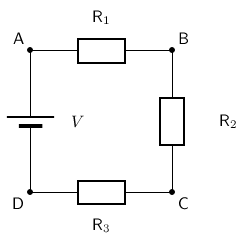
When there is more than one resistor in a circuit, we are usually able to calculate the total combined resitance of all the resistors. The resistance of the single resistor is known as equivalent resistance or total resistance. Consider a circuit consisting of three resistors and a single cell connected in series.
We can define the total resistance in a series circuit as:
For resistors in series the equivalent resistance is:
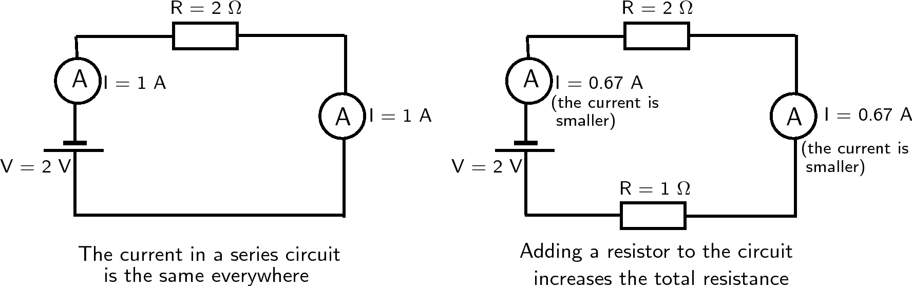
The more resistors we add in series, the higher the equivalent resistance in the circuit. Since the resistors act as obstacles to the flow of charge through the circuit, the current in the circuit is reduced. Therefore, the higher the resistance in the circuit, the lower the current through the battery and the circuit. We say that the current in the battery is inversely proportional to the resistance in the circuit. Let us apply the rule of equivalent resistance in a series circuit to the following circuit.

The resistors are in series, therefore:

Notification Switch
Would you like to follow the 'Siyavula textbooks: grade 10 physical science [caps]' conversation and receive update notifications?

|
|

|
|
|
|
|

|
|

|
|

|
|

|
|

|
|

|
|

|