| << Chapter < Page | Chapter >> Page > |
We conclude that if DOT and DOC are same then potential difference across resistor is negative and if they are opposite then the potential difference across resistor is positive.
The sign of power source is easier to decide. It merely depends on the direction of travel (DOT). Moving across a EMF source from negative to positive terminal is like moving from a point of lower to point of higher potential. Thus, if traveling across a source, we move from negative to positive terminal then potential difference is positive otherwise negative.
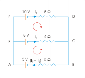
Combining above considerations, we write KVL equations for loops ABCFA and EDCFE as :
Voltage across circuit elements

Loop EDCFE (Starting from E) :
Loop ABCFA (Starting from A) :
Subtracting first from second we eliminate and we have :
Current in ED,
Current in BA,
Clearly, direction of current in each of the branch are opposite to the ones assumed.
Problem : Consider the network of resistors as shown here :
Network of resistors

Each resistor in the network has resistance 2 Ω. The EMF of battery is 10 V having internal resistance 1/6 Ω. Determine the equivalent resistance of the network.
Solution : We have seen in the earlier example that if I be the current, then current is distributed in different branches of the network as shown in the figure.
Network of resistors

Clearly, we need to determine current I in order to calculate equivalent resistance of the network. For this, we consider the loop ABCMA in clockwise direction. Applying KVL :
Let be the equivalent resistance of the network. Reducing given circuit and applying KVL in clockwise direction, we have :
Equivalent resistance

Consider the network of resistors as shown here :
Electrical network

Determine the equivalent resistance of the network between A and C.
In order to determine equivalent resistance, we assume that given network is connected to an external source of EMF equal to E. Now, the external EMF is related to effective resistance as :
Once this relation is known, we can determine equivalent resistance of the given network. It is important to note that current distribution is already given in the problem figure.
Electrical network

Considering loop ABCEA in clockwise travel, we have KVL equation as :
Considering loop ABDA in clockwise travel, we have KVL equation as :
We solve for to get an expression for it in terms of as :
Substituting above expression of in the equation obtained earlier for E, we have :
Putting this expression for in the expression obtained earlier for , we have :
But, we know that :
Thus,
Consider the network of resistors and batteries as shown here :
Electrical network

Find the currents in different braches of the network.
We assign currents with directions in different branches as shown in the figure. We can, however, assign current directions in any other manner we wish. Here, starting from and in branches CA and AB respectively and applying KCL at A, the current in AD is . Let the current in FE is . Applying KCL at B, current in BC is . Again applying KCL at C, current in CD is .
Electrical network

Considering loop ABCA in clockwise travel, we have KVL equation as :
Considering loop ADCA in anticlockwise travel, we have KVL equation as :
Considering loop BCDFEB in anticlockwise travel, we have KVL equation as :
We have three equations with three variables. Solving, we have :
Currents in different branches are :
Note that current in branch CD is negative. It means that current in the branch is opposite to the assumed direction.

Notification Switch
Would you like to follow the 'Electricity and magnetism' conversation and receive update notifications?