

| << Chapter < Page | Chapter >> Page > |

Halftone images are binary images that appear to have a gray scale rendition.Although the random thresholding technique described in "Binary Images" can be used to produce a halftone image, it is not often used in real applications since it yields very noisy results.In this section, we will describe a better halftoning technique known as ordered dithering .
The human visual system tends to average a region around a pixel instead of treating each pixel individually, thusit is possible to create the illusion of many gray levels in a binary image, even though there are actually only two gray levels.With binary pixel grids, we can represent 5 different “effective” intensity levels, as shown in [link] . Similarly for grids, we can represent 10 distinct gray levels. In dithering, we replace blocks of the original image with these typesof binary grid patterns.

Remember from "Binary Images" that false contouring artifacts can be reduced if we can reduce the signal dependence or the quantization error.We showed that adding uniform noise to the monochrome image can be used to achieve this decorrelation. An alternative methodwould be to use a variable threshold value for the quantization process.
Ordered dithering consists of comparing blocks of the original image to a 2-D grid, known as a dither pattern . Each element of the block is then quantized using the corresponding valuein the dither pattern as a threshold. The values in the dither matrix are fixed, but are typically different from each other. Because the thresholdvalue varies between adjacent pixels, some decorrelation from the quantization erroris achieved, which has the effect of reducing false contouring.
The following is an example of a dither matrix,
This is a part of a general class of optimum dither patterns known as Bayer matrices . The values of the threshold matrix are determined by the order that pixels turn "ON".The order can be put in the form of an index matrix . For a Bayer matrix of size 2, the index matrix is given by
and the relation between and is given by
where is the total number of elements in the matrix.
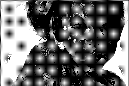
[link] shows the halftone image produced by Bayer dithering of size 4.It is clear from the figure that the halftone image provides good detail rendition. Howeverthe inherent square grid patterns are visible in the halftone image.
Another method for halftoning is random dithering by error diffusion . In this case, the pixels are quantized in a specificorder (raster ordering Raster ordering of an image orients the pixels from left to right, and then top to bottom. This is similar to the order that a CRT scans theelectron beam across the screen. is commonly used), and the residual quantization error for the current pixel is propagated (diffused) forward tounquantized pixels. This keeps the overall intensity of the output binary imagecloser to the input gray scale intensity.
Notification Switch
Would you like to follow the 'Purdue digital signal processing labs (ece 438)' conversation and receive update notifications?

|
|

|
|

|
|

|
|

|
|

|
|

|
|

|
|

|
|

|