

| << Chapter < Page | Chapter >> Page > |
The F5637's ADC can run off of one of several available clock signals of varying speeds. Once a sample has been captured, it is held ready in the ADC10MEMx registers for a defined number of clock cycles. Since we are concerned with a low frequency signal, we will want to slow down the ADC12 as much as possible. (Students who have had Elec241 will notice some fundamental flaws in the assumptions made regarding high-frequency noise, but in practice this has very little effect on the final results). Even in its slowest mode, the ADC12 will still sample too quickly, so the use of some kind of moving average will help stabilize its DC readings.
Your C program will be structured similarly to its assembly language counterparts, but with a much different syntax. Like before, the register names are all pre-defined in the
"msp430.h" header file. To set a register, now just use an equals sign and set it like any other variable. For example, you will want to disable the watchdog timer in the first line of your program.
WDTCTL=WDTPW+WDTHOLD; The compiler will execute the
void main(void) function first. From that function, you can call any other functions or run any loops that you would like.
#include<msp430.h>//Global Variable Declarations

//Global Function Declarationsint main(void)
{WDTCTL = WDTPW + WDTHOLD; // Stop WDT
   //Other Setup//Your Program Here
   //Can call other helper functions, loops, etc.return 0;
}
The ADC12 has two main control registers
ADC12CTL0 and
ADC12CTL1 , and 16 memory control registers
ADC10MCTLx (
12 bit
ADC
M emory
C o
N tro
L
0/1/2... channel 0-15). These registers control all the timing and conversion aspects of the ADC.
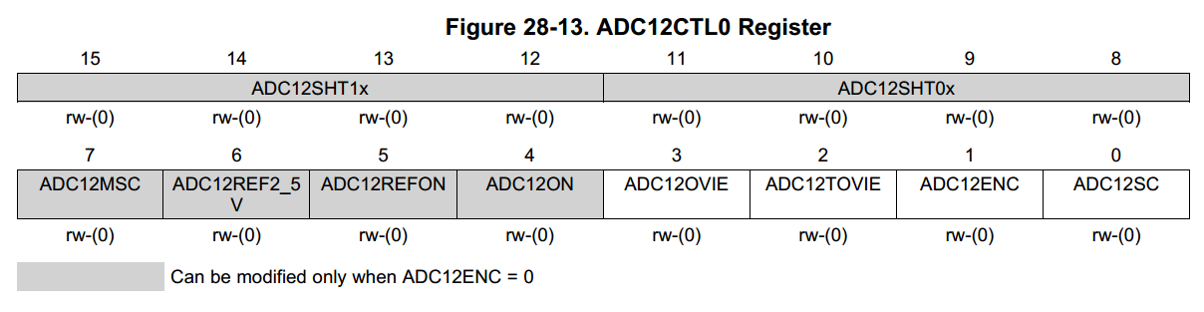
In the first control register (
ADC12CTL0 ), we only need to change two parameters,
ADC12SHT0_8 .ADC12ON ) turns on the ADC, a vital step to performing any conversion!ADC12CTL0 = ADC12SHT0_8 + ADC12ON ;
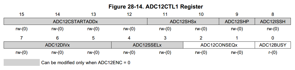
In the second control register (
ADC12CTL1 ), we want to set two parameters.
ADC12CTL1 = ADC12SHP + ADC12CONSEQ_0;
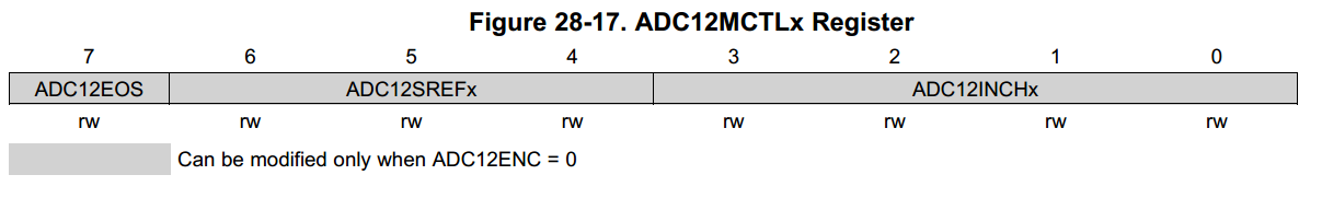
We also need to set the appropriate input channel to our output memory address in the ADC12MCTL0 register
ADC12MEM0 register.ADC12MCTL|= ADC12INCH_0;
Lastly, analog conversion must be enabled on the input ports themselves. These act as gates to prevent leakage current from flowing from a pin set as an output through the ADC to ground-- a substantial waste of power. To enable the ADC for your desired GPIO pin, just set the corresponding bit in
P6SEL (
P ort
6 Special Function
SEL ect) to "1".
P6SEL |= BIT#;
For more info about the ADC12's configuration options, see the MSP430 manual starting on page 742.
To read a sample from the ADC, just read from the ADC12MEM register after the sample has completed.
while (ADC12CTL1&ADC12BUSY); // Wait in naive loop for conversion to complete
my_var= ADC12MEM0; Remember that we have setup the ADC for single conversion and hold, so if you want another value, you will have to tell it to sample and convert again. You do so by modifying two values in ADC12CTL0:
ADC12CTL0 |= ADC12ENC + ADC12SC;
P3DIR register to display a value on the LEDs. You can configure the P3 registers using aliases and variable assignments just like with the ADC registers.Using Code Composer Studio 5, write a C language program turning your MSP430 ESCAPE Platform into a simple 10 level voltmeter. Your program should divide the 0-3.3V input range of the ADC into 10 zones, and then output from a 0 to a 9 on the LED display depending on the input voltage from the light sensor. Don't worry about a value landing on the boundary between two zones, just deal with it consistently. Test your volt meter by sampling pin P6.0 and exposing it to different light intensities.
Your Program should consist of:
Notification Switch
Would you like to follow the 'Elec 220 lab course (escape)' conversation and receive update notifications?

|
|

|
|

|
|

|
|

|
|

|
|

|
|
|
|
|

|
|
|
|