

| << Chapter < Page | Chapter >> Page > |
The operation of the IVEO System essentially consists of the following steps. These steps assume that your hardware and software system has been installed andtested.
Since I am assuming that you don't have access to either a touchpad or an embossing graphics printer, Iwill show you how to work around some of these steps. However, even with the workarounds, you should still be able toget a feel for the behavior of the system.
A complete Java program named Svg23.java is provided in Listing 2 .
The purpose of this program is to demonstrate how to use my graphics library named SvgLib21 (see Listing 26 here ) to create an SVG file containing a simple drawing that can be used with a common USB digitizertablet and the IVEO System .
All dimensions in the program are written in terms of the variables named width and height . Therefore, the only change that that you should need to make is toreplace the dimensions of my digitizer tablet with the dimensions of your digitizer tablet in the code fragment shown in Listing 1 .
Having done that, you should be able to compile and run the program and it should produce an output file named Svg23.svg .
| Listing 1 . Code requiring changes. |
|---|
//Change the following two values to the width and
    // the height of your digitizing pad in inches.double width = 5.0;
double height = 3.62; |
The image
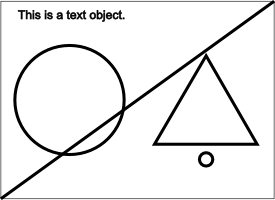
For the benefit of your assistant who will emboss your image, Figure 1 shows a reduced-size version of the image in the output SVG file for the dimensions of my digitizer tablet. Theimage should be very similar for the dimensions of your digitizer tablet.
| Figure 1 . Image from the file named Svg23.svg. |
|---|
 |
Description of the image
For your benefit, the image consists of a rectangle drawn with a thin line that is the same size as the active area on my digitizer tablet (5.0 x 3.62 inches) .
A circle with a radius of one inch is centered in the left half of the drawing.
A triangle, with its base parallel to the horizontal axis, is horizontally centered in the right half of the drawing.
A diagonal line extends from the lower left corner to the upper right corner of the drawing.
Notification Switch
Would you like to follow the 'Accessible physics concepts for blind students' conversation and receive update notifications?

|
|

|
|

|
|
|
|
|

|
|

|
|

|
|

|
|

|
|

|