This module contains step by step instructions and pictures showing how to assemble the MSP430 breadboard kit used in Elec 220 for very simple I/O. It uses the TI MSP430 Launchpad development board, a double breadboard, and some basic circuit components (switches and a 7-segment display) to establish an easy to understand I/O scheme.
Breadboard basics
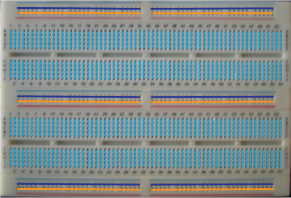
The solder-less breadboard is a convenient way to setup simple circuits and make connections quickly between electronic components. Each hole in the breadboard has a spring clip that makes a connection to the wire/ IC lead you put into it.
The breadboard connects each vertical row of holes in the main secion , giving you five holes where you can tie together parts of an electrical circuit. Any time there is a gap between two adjacent holes, they are not automatically connected together.
You will notice some red and blue horizontal lines of holes in the top, bottom, and middle of the breadboard. These are your
busses . In most simple breadboards you will use these for power (VCC and GND) as we do here. The bus sections are not automatically connected together. If you want power to all of the busses, you need to connect them all together as shown below.
Lastly, notice the divided
channel down the middle of the breadboard. This channel is specifically sized for DIP packaged integrated circuits. You can put a chip across the channel, and have access to each of its pins using the vertical rows above and below. Always put chips across the channel, otherwise you will connect the opposite side pins together and your circuits won't work as expected.
Be careful when removing chips
If you use your bare hands to try and remove a chip from the breadboard (you will notice it can be difficult, especially with components with lots of pins), there is a good chance you will end up with the chip plugged into your finger afterwords. You hand has a natural tendency to rotate things when you are pulling hard, so watch out.
There are some IC removing tools around the lab, use one of them or ask your labbies to help you if you accidentally misplace a chip.
The connection scheme in a typical breadboard
An illustration of how the breadboard holes are connected together in the breadboards used for the lab. Notice that no connections cross the center channel and that the busses are connected horizontally while the main face of the board is vertical.
Steps for assembling the breadboard for elec 220
Make all connections with the MSP430 disconnected from USB power.
Be careful when removing chips
See above for explanation.
Use an IC removal tool or ask your labbies for help.
Tinkerers:
The wiring below is suggested and works well, but if you have any ideas on how to improve the circuit, feel free to implement them in your breadboard. Just be sure that you can successfully run the test program at the end.
Receive real-time job alerts and never miss the right job again
Source:
OpenStax, Intro to computational engineering: elec 220 labs. OpenStax CNX. Mar 11, 2013 Download for free at http://cnx.org/content/col11405/1.2
Google Play and the Google Play logo are trademarks of Google Inc.
Notification Switch
Would you like to follow the 'Intro to computational engineering: elec 220 labs' conversation and receive update notifications?