<< Chapter < Page Chapter >> Page >
This module presents introductory material on data communication, focusing on a high-level summary/comparison of analog and digital communication.

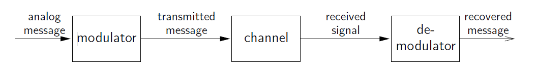
Goal: Transmit a message from one location to another.

When message is a...
continuous waveform, use analog comm (e.g., FM radio),
sequence of numbers, use digital comm (e.g., mp3 file),
but keep in mind that the sequence of numbers might represent a sampling of a continuous waveform (as in the case of digital audio).

Typical communication media:

twisted pair wire (e.g., telephone A )
coaxial cable (e.g., TV A , D , data D )
fiber optic cable (e.g., ethernet D )
EM waves (e.g., cellular phones A , D , WiFi D , TV A , D )
water waves (e.g., underwater network A , D )
power lines A , D
compact disc D
hard drive D
magnetic tape A , D

where A = analog and D = digital.

Note that, whether the message signal is discrete-time or continuous-time, the transmitted signal is continuous-time!

Analog communication

This is a flowchart with movement to the right. It begins with an arrow moving to the right, labeled analog message. The arrow points at a box labeled modulator. To the right of the box is another arrow pointing to the right, labeled transmitted message. This arrow points at a box labeled channel. To the right of the channel box is an arrow pointing to the right, labeled received signal. To the right of this arrow is a box labeled de-modulator. Following this is a final arrow, pointing to the right, labeled recovered message. This is a flowchart with movement to the right. It begins with an arrow moving to the right, labeled analog message. The arrow points at a box labeled modulator. To the right of the box is another arrow pointing to the right, labeled transmitted message. This arrow points at a box labeled channel. To the right of the channel box is an arrow pointing to the right, labeled received signal. To the right of this arrow is a box labeled de-modulator. Following this is a final arrow, pointing to the right, labeled recovered message.
  • Perfect recovery is impossible in the presence of noise!

Digital communication

This is a long flowchart moving to the right, with labeled arrows pointing at  boxes to their right. The first arrow is labeled binary message, with the label below, ... 010110 .... This is followed by a box labeled coder/mapper. To the right of this is an arrow labeled symbol sequence, ... 3, -1, 1, -3 ... After this is a box labeled pulse shaper. To the right of this is an arrow labeled baseband message, with a small graph showing a wave and a half. This arrow points at a box labeled modulator. To the right of this is an arrow labeled passband message. This arrow points at a box labeled channel. to the right of this is an arrow labeled received passband. This points at a box labeled demodulator. To the right of the box is an arrow labeled received baseband. This points at a box labeled sampler. To the right of the sampler box is an arrow labeled received sequence. This arrow points at a box labeled equalizer. To the right of this box is an arrow labeled equalized sequence, with a numbered sequence below, ... 3.1, -0.9, 1.1, -2.9 ... This arrow points at a box labeled de-mapper/decoder. To the right of this is a final arrow labeled recoevered message ... 010110 ... This is a long flowchart moving to the right, with labeled arrows pointing at  boxes to their right. The first arrow is labeled binary message, with the label below, ... 010110 .... This is followed by a box labeled coder/mapper. To the right of this is an arrow labeled symbol sequence, ... 3, -1, 1, -3 ... After this is a box labeled pulse shaper. To the right of this is an arrow labeled baseband message, with a small graph showing a wave and a half. This arrow points at a box labeled modulator. To the right of this is an arrow labeled passband message. This arrow points at a box labeled channel. to the right of this is an arrow labeled received passband. This points at a box labeled demodulator. To the right of the box is an arrow labeled received baseband. This points at a box labeled sampler. To the right of the sampler box is an arrow labeled received sequence. This arrow points at a box labeled equalizer. To the right of this box is an arrow labeled equalized sequence, with a numbered sequence below, ... 3.1, -0.9, 1.1, -2.9 ... This arrow points at a box labeled de-mapper/decoder. To the right of this is a final arrow labeled recoevered message ... 010110 ...
  • A digital message is converted to an analog message coding and pulse-shaping, and then transmitted usinganalog modulation. To recover the message, the received signal is demodulated, sampled, and digitally processed.
  • Perfect recovery is possible even in the presence of noise!

Get Jobilize Job Search Mobile App in your pocket Now!

Get it on Google Play Download on the App Store Now


Source:  OpenStax, Introduction to analog and digital communications. OpenStax CNX. Sep 14, 2009 Download for free at http://cnx.org/content/col10968/1.2
Google Play and the Google Play logo are trademarks of Google Inc.

Notification Switch

Would you like to follow the 'Introduction to analog and digital communications' conversation and receive update notifications?

Ask