

| << Chapter < Page | Chapter >> Page > |
The problem of timing recovery is to choose the instants at which to sample the incoming (analog) signal. This can betranslated into the mathematical problem of finding a single parameter, the timing offset , which minimizes (or maximizes) some function(such as the source recovery error, the cluster variance, or the output power) of given the input. Clearly, the output of the sampler mustalso be a function of , since specifies when the samples are taken.The first step is to write out exactly how the values of the samples depend on . Suppose that the interval between adjacent symbols is known exactly.Let be the pulse shaping filter, the receive filter, the impulse response of the channel, the data from the signal alphabet,and the noise. Then the baseband waveform at the input to thesampler can be written explicitly as
Combining the three linear filters with
as shown in [link] , and sampling at interval ( is again the oversampling factor ) yields the sampled output at time :
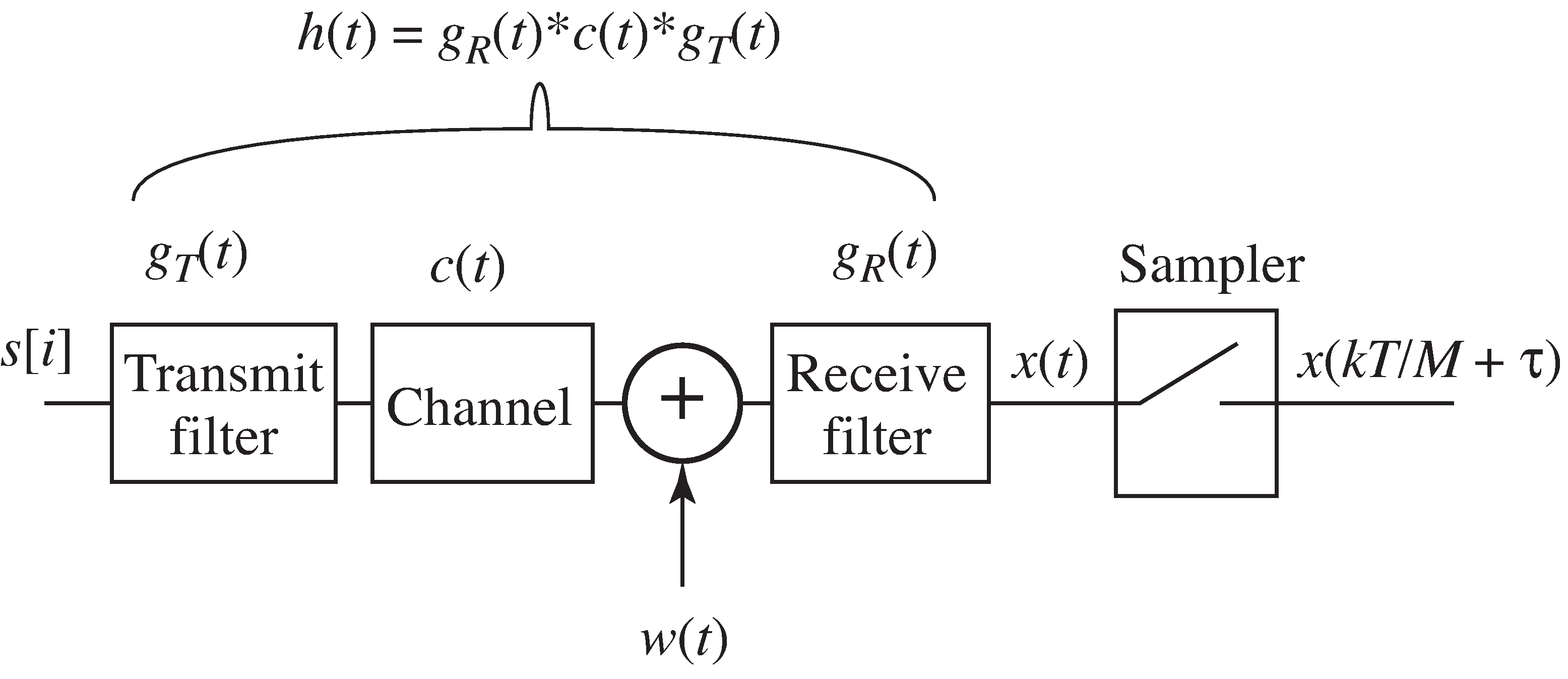
Assuming the noise has the same distribution no matter when it is sampled, the noise term is independent of . Thus, the goal of the optimization is to find so as to maximize or minimize some simple function of the samples, such as
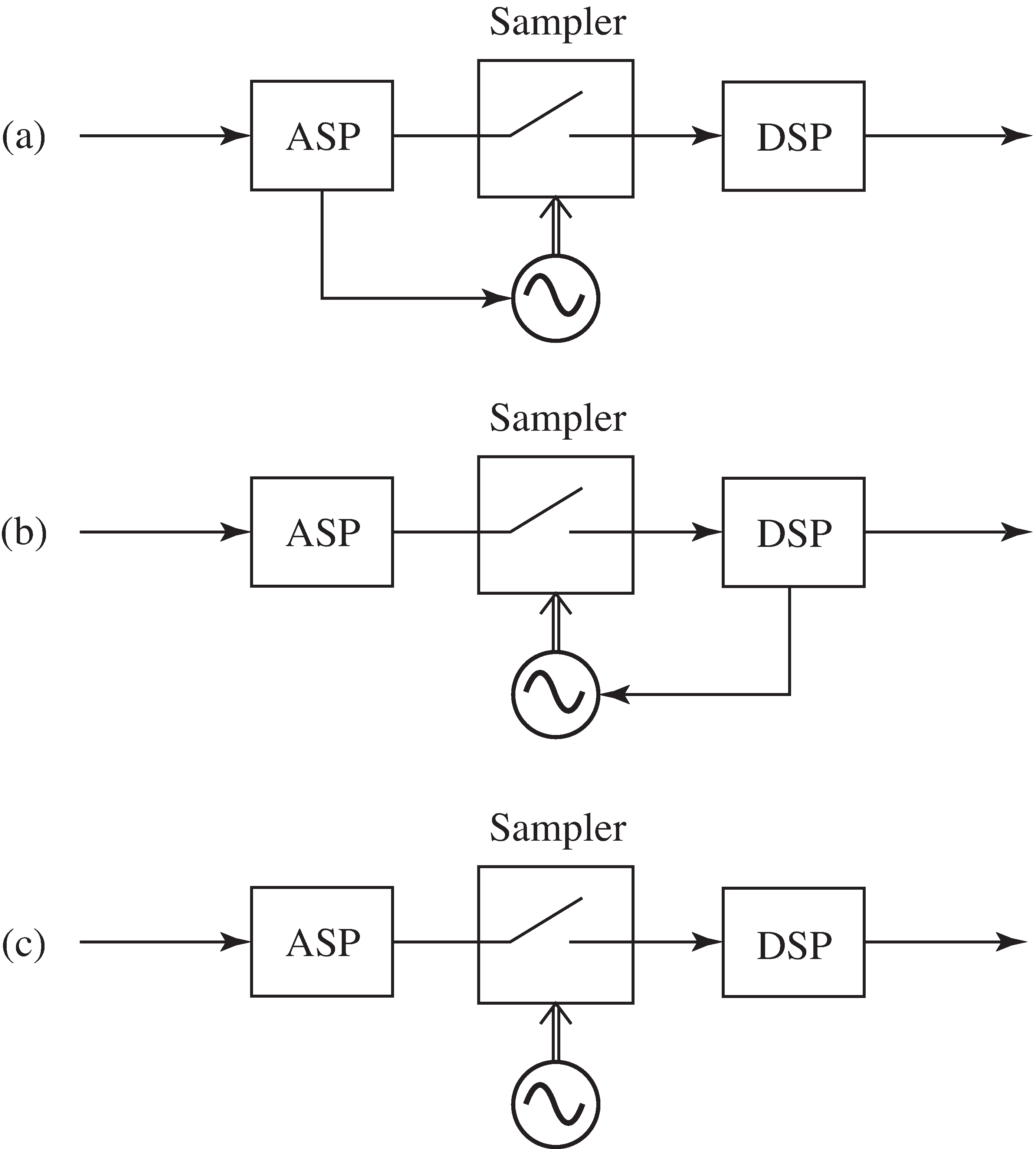
There are three ways that timing recovery algorithms can be implemented, and these are shownin [link] . In the first, an analog processor determines when thesampling instants will occur. In the second, a digital post processor is used to determine when to sample. In thethird, the sampling instants are chosen by a free running clock, and digital post processing (interpolation) is used torecover the values of the received signal that would have occurred at the optimal sampling instants.The adaptive elements of the next sections can be implemented in any of the three ways,though in digital radio systems the trend is to remove as much of the calculation from analog circuitry as possible.
This section works out in complete and gory detail what may be the simplest caseof timing recovery. More realistic situations will be considered (bynumerical methods) in later sections.
Consider a noise-free binary baseband communication system in which thetransmitter and receiver have agreed on the rate of data flow (one symbol every seconds, with an oversampling factor of ). The goal is to select the instants at which to sample, that is, to find the offset . Suppose that the pulse shaping filter is chosenso that is Nyquist; that is
Notification Switch
Would you like to follow the 'Software receiver design' conversation and receive update notifications?

|
|

|
|

|
|

|
|

|
|

|
|

|
|

|
|

|
|

|