

| << Chapter < Page | Chapter >> Page > |
On some level, every signal and every interface starts out analog. In this lab you will learn a simple two point calibration routine and how to use it to get accurate data from the physical world. This assignment is less about new programming principals and more about applying what you already know. You have one main task:
The analog voltmeter may seem simple, but the ability to measure and quantify an analog voltage allows the MSP430 to interface with a whole range of analog sensors. Ultimately, any real world signal starts out analog, so at the heart of every interface lies some kind of analog system..
Analog sensors use the physical properties of some electronic device (or a system of many devices) to modify an analog voltage or current signal. The MSP430's ADC allows it to use that signal in computations (as long as the signal's maximum frequency is less than 100khz- the nyquist sampling frequency of the 200khz ADC). In simple terms, the ADC can't accurately measure signals that change too quickly for it to see. Not only that, but the ADC can pickup unwanted distortion from those higher frequency signal components, making even the low frequency parts inaccurate.
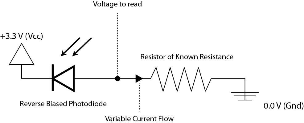
A photodiode is just one of many such devices. When kept in reverse voltage bias, the photodiode allows an amount of current through it proportional to the amount of light shining onto it. By attaching a photodiode in series with a resistor, we can examine the voltage across the resistor to find that current (v=i*R), and therefore the relative amount of light!
For simplicity, we're going to use the pre-built light sensor circuit on the ESCAPE platform. It is a little bit more complicated than the one above. As you continue to take more courses and learn more about analog electronics, you will be able to design your own analog circuits to capture and condition the information you want.
In this last lab you'll be using the full repertoire of I/O options available to you. You'll use the ADC to read an analog voltage, the pushbuttons and interrupts to control a calibration routine, and the 7-segment display to output a measured number.
Notification Switch
Would you like to follow the 'Elec 220 lab course (escape)' conversation and receive update notifications?

|
|

|
|

|
|

|
|

|
|

|
|

|
|

|
|

|
|

|